blog
Building a small custom Raspberry Pi Zero laptop in a cardboard box
by snm, November 12th, 2017

Making the Pi Zero portable. Starting off with:
USB
First of all, the Pi Zero has two microUSB ports, one for power and another for USB devices. With a USB on-the-go cable, converting to female USB-A, we can plug in one USB device. Not enough. To expand to four ports, picked up this little hub, the Monoprice Aquamini:
Networking
Networking is crucial in any computer in the era of the Internet. With the hub adding four USB ports, I decided to use two of them for network interfaces, wired and wireless:
- USB Ethernet adapter
- USB Wi-Fi adapter
I used spare adapters I had on hand, but for a new project the Miniature WiFi (802.11b/g/n) Module: For Raspberry Pi and more may work better.
Keyboard
An input device is necessary for a laptop as well. Selecting a suitable keyboard is a difficult choice, a balance between portability and usability. Adafruit’s 6” x 2.4” x 0.5” Miniature Wireless USB Keyboard with Touchpad looks promising but the keys are too small for my taste. Or their 11.2” x 4.7” x 0.8” Wireless Keyboard and Mouse Combo w/ Batteries - One USB Port!, bigger but too wide. The solution? I settled on a foldable keyboard, from Amazon:
It may be overkill, but I needed another extra keyboard anyways, and this one supports both USB and Bluetooth (for use with other projects - no Bluetooth here).
Battery
We need a battery. There are lithium batteries and chargers available but I already had an old Morphie Juice Pack, intended for smartphones but since it has a female USB-A (for charging) and microUSB port (for supplying power), it can be used here too. The charging port is useful, since it can be powered from the original USB wall wart. It does require another cable, however, and I ran out (for some reason, I have a surplus of mini USB cables, but now those are obsoleted by micro USB, just my luck), headed to Aliexpress for some cheap micro USB cables (80¢ each, ordered several):
In the meantime, I used the long flat microUSB cable from my 8bitdo NES30, it coils up nicely within the box:

Display
The display is perhaps the most noticeable component in a laptop. There are a lot of choices here. Using an HDMI display is the obvious choice, since the Pi Zero has a mini HDMI connector (and the budget pack comes with a mini HDMI to HDMI adapter). For use with an external DVI display, I purchased from Monoprice:
There are a variety of small HDMI displays available, including resistive touchscreens. The Pi Foundation also makes an official Raspberry Pi Touch Display, but it uses the DSI (display serial interface) port, present on the Raspberry Pi 3 but not the Zero, so that’s out. There are also displays using SPI and GPIO, such as PiTFT Plus 480x320 3.5” TFT+Touchscreen for Raspberry Pi.
How about epaper/eink? The Pi Supply PaPiRus Zero ePaper/eInk pHAT v1.2 looks quite nice, but electronic paper has an extremely slow refresh rate (~1 Hz?), it wouldn’t be the most suitable for an interactive terminal, I’d wager. The Adafruit Sharp Memory Display Breakout is a hybrid of eInk (e-paper) and LCD, but still I would be concerned about slow refresh rate, and it was out of stock.
With all these choices to choose from, I opted for an unorthodox choice: monochrome OLEDs. Low resolution and no color, but they are quite small and should be sufficient for simple text or trivial graphics. And I’ve already set them up in the previous blog posting, Monochrome 2.7” and 2.42” 128x64 OLED displays on a Raspberry Pi Zero, but here are the product links again:
- Monochrome 2.7” 128x64 OLED Graphic Display Module Kit
- Monochrome 2.42” 128x64 OLED Graphic Display Module Kit
You can get smaller OLEDs, but these beefy displays ought to present a reasonable amount of information for my purposes. At least, much more than feeble 7-segment LED displays.
Case
Ah, the case. Could easily order a pi-top and be done with it (the entire laptop, in fact), but that’s no fun. More fun would be to design a 3D model and get it made with a 3D printing service such as Shapeways or Sculpteo. Find one on Thingiverse, this one by surferboy: Raspberry pi laptop, looks very nice, but its for a Pi Model B+, with its fancy DSI touchscreen, not the Pi Zero. Design a case, order it printed or get a 3D printer… I’ll pass, for now, what do I have readily available on hand?
Since I ordered a bunch of products from Adafruit (disclaimer: not endorsed by or affiliated with, merely a customer), I have this extra cardboard shipping box:

The foldable iClever keyboard barely fits into this box, when placed diagonally. So I began to cut holes into it, but then I found another appealing cardbox box, a flatter and wider shipping box from Sparkfun, measuring 7.25” x 5” x 1.75”. The iClever foldable keyboard perfectly fits on top:

and there is room for the components on the bottom, pictured here the Monoprice 4-port USB hub:

Cutting holes for USB ports
The hub fits nicely in the corner, with two ports facing outside and two inside (for the Wi-Fi and Ethernet). Trace around the connector with a pencil, then cut out holes with an X-Acto knife. I cut the side hole first, moved the hub into it, then cut the back hole - it didn’t move too much since the cardboard in the back was thinner. Then for the indicator LED on the hub, affix double-sided tape over it, color with permanent marker, press it down to know where to cut next:

with the hub snugly fit into place:

To allow the box to close, the left tab needs to be shaved down as well:

SPI display connection
All of the connectors for the SPI display are conveniently located in a 4x2 block on the Pi header. A cable with a 4x2 female connector would work well, unfortunately I didn’t have one. But I do have female-to-male jumper wires, and a 170 tie miniature breadboard. Fits in the box, but perpendicular angling of the jumpers and the breadboard makes it not curve around the hinge of the box very well. A ribbon cable would be useful here; ordered a Raspberry Pi 3 40 Pin Extension Board Adapter +40 Pin GPIO GPIO Cable Line For Banana Pi M3 /Raspberry Pi 2/ For Orange Pi PC from Aliexpress for $2.67, this breakout board shows the pinout making wiring easier. Until it arrives, I went ahead and soldered the jumper wires themselves (not recommended) onto the OLED module.
Admittedly this is a waste of perfectly good prototyping jumper wires, but there wasn’t much else I could do, and I have some more on the way from Aliexpress: Dupont line 120pcs 10cm male to male + male to female +female to female jumper wire Dupont cable for arduino. A better solution may be to use a female connector, but I also lack one with 20-pins, though it would be possible to use an 8-pin and 2-pin female connector, connecting would still be problematic. The header is soldered onto the bottom of the module, it could be soldered onto the top but then the cable would block the view. Right-angle headers may help, or not really.
For now, although it is an ugly hack, the 20-pin header can be (carefully) pushed into the cardboard, acting as a makeshift mounting mechanism. Careful to not bend the board too much: ceramic capacitors can crack if bent, leading to shorts; so I pressed the pins into the board gently, then punched through to the other end with another unsoldered header. That was easy:
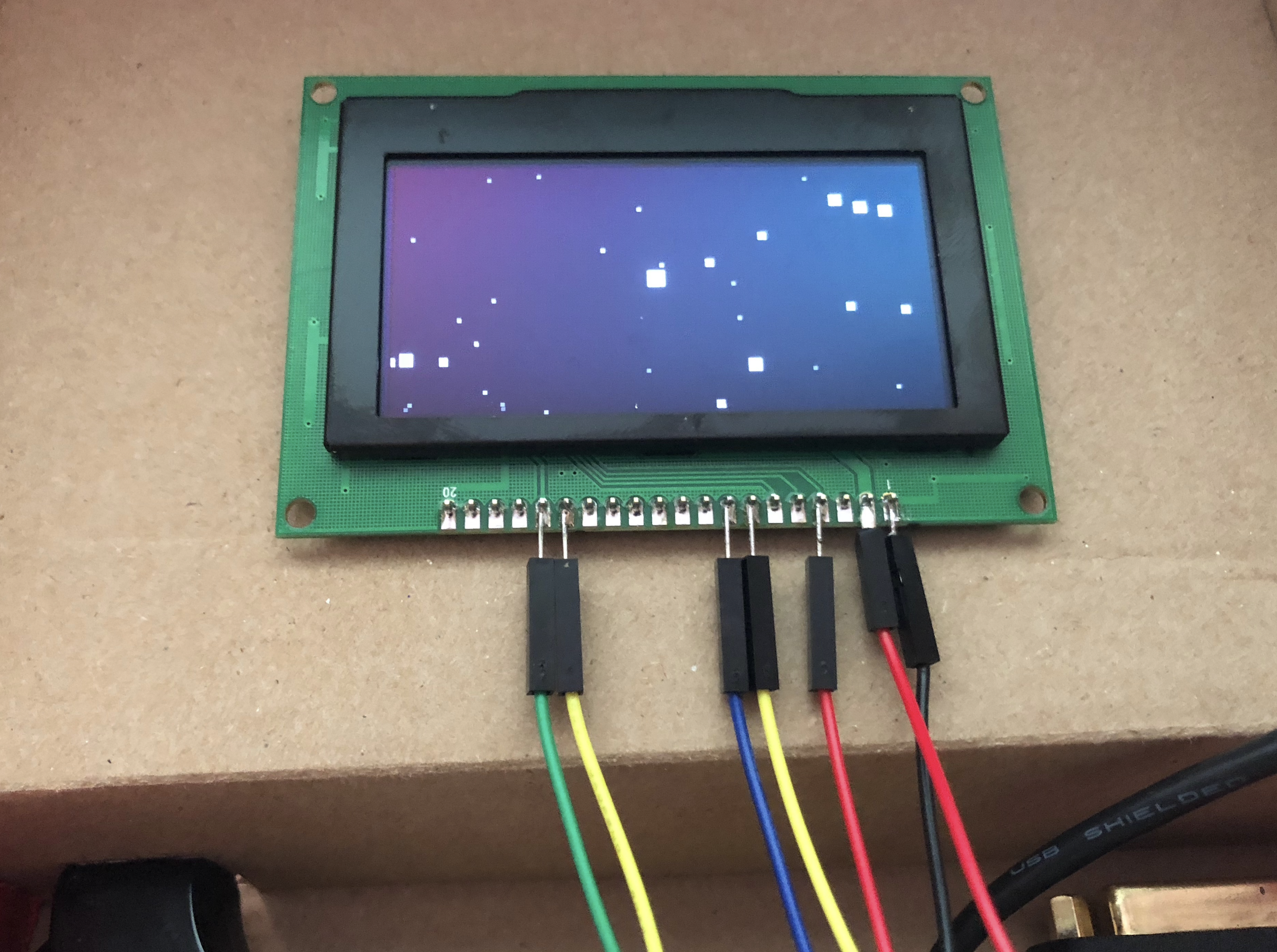
Testing the display with:
python luma.examples/examples/starfield.py --display ssd1325 --interface spi
Note that it is mounted up-side down! This is more apparent with the clock example:

The orientation will need to be corrected in software. With luma.oled, this can be accomplished using the --rotate 2 flag in their examples.
Important note: This OLED display doesn’t display the desktop or console. Software will need to be written to allow interacting with this display using the keyboard (see below).
External video port
The DVI-to-HDMI and HDMI-to-mini-HDMI connectors fit well on the right side of the box. DVI is a big enough of a connector that it slides into the cardboard securely, after cutting out a hole around its outline. The connector is flush with the wall:

I added the DVI adapter because that’s the kind of external monitor I have, but it could be omitted if you have or want to use external HDMI displays instead. Here’s a view from the outside, showing both DVI and the rear USB:

Here is an external DVI monitor connected, showing it works (the box is underneath the keyboard, you can barely see it):

Ethernet port
The USB-to-Ethernet adapter is fairly straightforward to add, but one caveat is that if it was flush up against the right side of the box, then the box couldn’t close. To fix this, I bent some leftover cardboard, affixed with double-sided tape, to act as a spacer:

then trace the connector outline with a pencil and cut the cardboard with an X-Acto knife as usual. Here’s the Ethernet port directly above the DVI port:

Here is an annotated picture of all the external ports available in this amazing laptop:

Battery connection
The Morphie juice pack is thin and flat, so it won’t be too much trouble to fit inside this case. Both of its ports are on the same side, and it also has a small “battery” button in the corner, which when pressed lights up up to four LEDs indicating the charge level and charging progress. It would be nice to make this input and output accessible within the laptop (even cooler, to monitor in digitally, but not yet).
To monitor power usage, we could use a “USB safety tester” such as Digital Display 3V-30V USB Tester Current Voltage Charger Capacity Doctor qc2.0/3.0 quick charge power bank meter voltmeter, inline with the battery. Ordered from Aliexpress, awaiting delivery.
The long USB cables are cumbersome, but the juice pack fits neatly (well, almost) on top of the USB hub. Secure it to the back with double-sided tape, taking care to leave some clearance on the left to allow the box to close. Before installing the battery:

With the battery (before sticking together with tape - mind the gap on the left side):

Almost fits, but the fat USB-A connector extends too far, colliding with the Ethernet adapter, raising the battery pack up too high. It isn’t pretty, but it fits better when rotated diagonally:

The battery status button is below the LEDs, and the charging port is above the USB power cable. Unfortunately with this design, the charging port is not exposed externally. Wouldn’t want the power cable to be protruding externally too. Maybe this could be solved by a microUSB extension cable of some sort. Micro B USB 2-Way Y Splitter Cable? Ordered a micro USB 2-way Y splitter (female to data/charge) from Aliexpress for $1.32, yet another cable to stuff in this box but it’ll be nice to have an external charging port:
Another significant downside is the Morphie cuts off power when it is charging! If I didn’t have it already, I probably wouldn’t use this Morphie juice pack as a laptop battery, and instead use something like PowerBoost 1000 Charger - Rechargeable 5V Lipo USB Boost @ 1A - 1000C, which is advertised as thus: “With a built-in load-sharing battery charger circuit, you’ll be able to keep your power-hungry project running even while recharging the battery!”
TODO: in absense of load sharing, an external power port bypassing the battery would be quite useful
Warning: This laptop design also currently lacks a power switch. To turn it off, login and run sudo shutdown now. To turn back on, you have to open it and unplug and plug the USB power cable back into the power brick. Inelegant, I know :(
Keyboard
For compactness, the keyboard folds up for storage, and has to be unfolded for usage. Here is the complete box, stowed away:

Open it up and you will find the folded keyboard:

Unfold it and plug in the bundled USB cable, into the micro USB port on the keyboard, and a side USB port on the “laptop” (if you can call it that):

Not ideal, but hey. Replacing the cable with a more compact (right-angle?) micro USB cable could go a long way, but at least this is functional.
Activity LED
The singular LED on the Pi Zero, the activity LED (“ACT”), is deep within the bowels of the laptop. Measured a 1.9 V voltage drop across the LED, with the negative terminal by the camera connector. This LED can be controlled using GPIO as described in Controlling PWR and ACT LEDs on the Raspberry Pi, but I’m more interested in making the LED visible from the outside.
Putting a green LED in parallel (short lead next to camera connector) with the onboard ACT LED works as you would expect. Cut a small hole in the front panel of the cardboard, pop the LED through, then very carefully solder on the leads, its a tight squeeze but possible:

Here’s how it looks in the dark:

Additional external indicator LEDs could be added and driven through the GPIO pins, currently with the OLED display module only SPI channel 0 and two GPIOs (for DC and RST) are used, everything else is available. But for now, the front panel only shows the activity LED.
Weight
How much does this thing weigh? Testing on a scale, it clocks in at about 1.4 pounds:

Console terminal on OLED
The OLED module is driven over SPI, so it doesn’t display the desktop or console you would see over HDMI video output. To make it useful, we’ll need to write some code. luma.examples terminal is a good start, try it like this:
python terminal.py --display ssd1325 --interface spi --rotate 2
but it only prints lines of text, doesn’t provide any input or other terminal capabilities. Using the Linux framebuffer, see How to use /dev/fb0 as a console from userspace, or output text to it, may be interesting. Or /dev/console. fbset? sudo showkey doesn’t seem to work over SSH to capture the keys pressed on a USB keyboard. w, cat /dev/tty1? The Linux input subsystem creates /dev/input/, per this StackOverflow post from 2009 How can you read keystrokes when the python program isn’t in the foreground?, but it only contains mice on my system (no keyboard. And I don’t even have a mouse). How about sudo screendump, this command looks promising:
pi@pizero:~/oledterm $ sudo screendump


         Starting Hold until boot process finishes up...
         Starting Terminate Plymouth Boot Screen...

Raspbian GNU/Linux 9 pizero tty1
pizero login: pi (automatic login)
Last login: Mon Nov 13 01:15:33 UTC 2017 from 172.16.0.50 on pts/1
Linux pizero 4.9.59+ #1047 Sun Oct 29 11:47:10 GMT 2017 armv6l

The programs included with the Debian GNU/Linux system are free software;
the exact distribution terms for each program are described in the
individual files in /usr/share/doc/*/copyright.

Debian GNU/Linux comes with ABSOLUTELY NO WARRANTY, to the extent
permitted by applicable law.

SSH is enabled and the default password for the 'pi' user has not been changed.
This is a security risk - please login as the 'pi' user and type 'passwd' to set a
 new password.

hi@pizero:~ $
It says it is the same as reading /dev/vcsa. We could scrape the virtual console, then copy it to the OLED screen. In the tiny.ttf font (size 6), can fit 9 rows, and 28 columns. This is extremely rough, but it is enough to show at least the concept of reading from the virtual terminal to print to the OLED:
#!/usr/bin/env python
# -*- coding: utf-8 -*-
# based on:
# Copyright (c) 2014-17 Richard Hull and contributors
# See LICENSE.rst for details.
# PYTHON_ARGCOMPLETE_OK

import os
import time
import sys
from luma.core import cmdline
from luma.core.virtual import terminal
from PIL import ImageFont

VIRTUAL_TERMINAL_DEVICE = "/dev/vcsa"
ROWS = 9
COLS = 28

# based on demo_opts.py
from luma.core import cmdline, error
def get_device(actual_args=None):
    """
    Create device from command-line arguments and return it.
    """
    if actual_args is None:
        actual_args = sys.argv[1:]
    parser = cmdline.create_parser(description='luma.examples arguments')
    args = parser.parse_args(actual_args)

    if args.config:
        # load config from file
        config = cmdline.load_config(args.config)
        args = parser.parse_args(config + actual_args)

    # create device
    try:
        device = cmdline.create_device(args)
    except error.Error as e:
        parser.error(e)

    #print(display_settings(args))

    return device

# based on luma.examples terminal
def make_font(name, size):
    font_path = os.path.abspath(os.path.join(
        os.path.dirname(__file__), 'fonts', name))
    return ImageFont.truetype(font_path, size)


def main():
    if not os.access(VIRTUAL_TERMINAL_DEVICE, os.R_OK):
       print "Unable to access %s, try running as root?" % (VIRTUAL_TERMINAL_DEVICE,)
       raise SystemExit

    fontname = "tiny.ttf"
    size = 6

    font = make_font(fontname, size) if fontname else None
    term = terminal(device, font, animate=False)

    term.println("oledterm starting...")
    time.sleep(1)

    while True:
        data = file(VIRTUAL_TERMINAL_DEVICE).read()
        term.clear()
        term.println(data)
        term.flush()
        time.sleep(2)


if __name__ == "__main__":
    try:
        device = get_device()
        main()
    except KeyboardInterrupt:
        pass
To start it up on boot, I added to the end of /etc/rc.local, before exit 0, to run it in the background:
python /home/pi/oledterm/oledterm.py --display ssd1325 --interface spi --rotate 2 &
This gives us a peak into the console:

The next step would be to finish writing the oledterm program, so that it either sets the virtual console to 9x28, or otherwise efficiently bridges the virtual console to the OLED module, allowing its use as a fully-fledged terminal console.
Updated November 15th, 2017: On Linux, the stty rows and stty cols commands can be used to limit the virtual console to a smaller text resolution than the maximum size supported by the current font size and graphical resolution. With this in mind, mirroring the console to the OLED module is straightforward, allowing for a fully interactive shell and terminal, no need to reimplement either:

This technique even allows running full-screen programs such as vi:

Updated code is available at: https://github.com/satoshinm/oledterm
The end
This concludes this blog post describing the construction of this custom Raspberry Pi Zero laptop, at least for now. There is a lot of work to be done to make it into a generally usable computing device, but its a start, you have to start somewhere. To end with, here is one last picture of the final laptop:
