blog
Building an Amazing $10 Oscilloscope with an STM32 blue pill, LCD touchscreen, and STM32-O-Scope software
by snm, January 5th, 2017
An oscilloscope is an essential tool for any electronics engineer. A popular inexpensive digital signal oscilloscope is the Rigol DS1054Z, supporting 4 analog channels and 50 MHz bandwidth. But it retails for $349, probably a worthwhile investment for a professional but steep for a casual hobbyist. Fortunately, with about $10 in parts it is possible to build a minimal oscilloscope, sporting only 1 analog channel at ~2 MHz bandwidth maximum. Not in the league of “real” commercial oscilloscopies, but still powerful enough to be useful.
Based on Andy Hill’s project, pingumacpenguin/STM32-O-Scope: STM32F103 based minimalist oscilloscope., in turn based on Ray Burnette’s idea. See also this thread on stm32duino forums: $10 O-Scope revisited by ahull on May 09, 2015. All credit goes to them, I’m only following instructions.
Parts list
- $1.70 STM32F103C8T6 ARM STM32 Minimum System Development Board Module
- $9.20 1pcs J34 F85 240x320 2.8” SPI TFT LCD Touch Panel Serial Port Module with PCB ILI9341 5V/3.3V
Total $10.90.
Constructing the hardware
Follow the construction instructions on their wiki for how to wire up the display to the microcontroller.
One confusing part of the steps is that it says “Hardware SPI1 on the STM32F103C8T6 ALSO needs to be connected and pins are as follows.” then lists “SPI1_NSS (PA4) (LQFP44 pin 14) (n.c.)”, but n.c. means not-connected. PA4 is the slave select pin, also known as S̅S̅, SSEL, CS, C̅S̅, CE, nSS, /SS, or SS#. In this case they capitalized nSS as NSS. To be clear, PA4/NSS does not need to be connected.
Secondly, the instructions said “SPI1_MOSO (PA6) (LQFP48 pin 16) (White)” but there isn’t a MOSO master out / slave out label on my display, in contrast to “SPI1_MOSI (PA7) (LQFP48 pin 17) (Grey)” they probably meant MISO. Got it reversed the first time, but worked after swapping. To summarize here are all the connections that worked for me:
| STM32 blue pill board | ILI9341 LCD display board | Remarks |
|---|---|---|
| A0 | D/C | Data/command |
| A1 | CS | Chip select |
| A2 | RESET | Reset |
| A3 | LED | Onboard LED |
| A4 | (not connected) | Slave select, not used |
| A5 | SCK | SPI clock |
| A6 | SDO(MISO) | SPI master input / slave output |
| A7 | SDI(MOSI) | SPI master output / slave input |
| G | GND | Ground |
| 3.3 | VCC | Power |
| B0 | (free wire) | Analog input |
| B1 | (free wire) | Test signal, 500 Hz square wave |
And how it looks wired up:
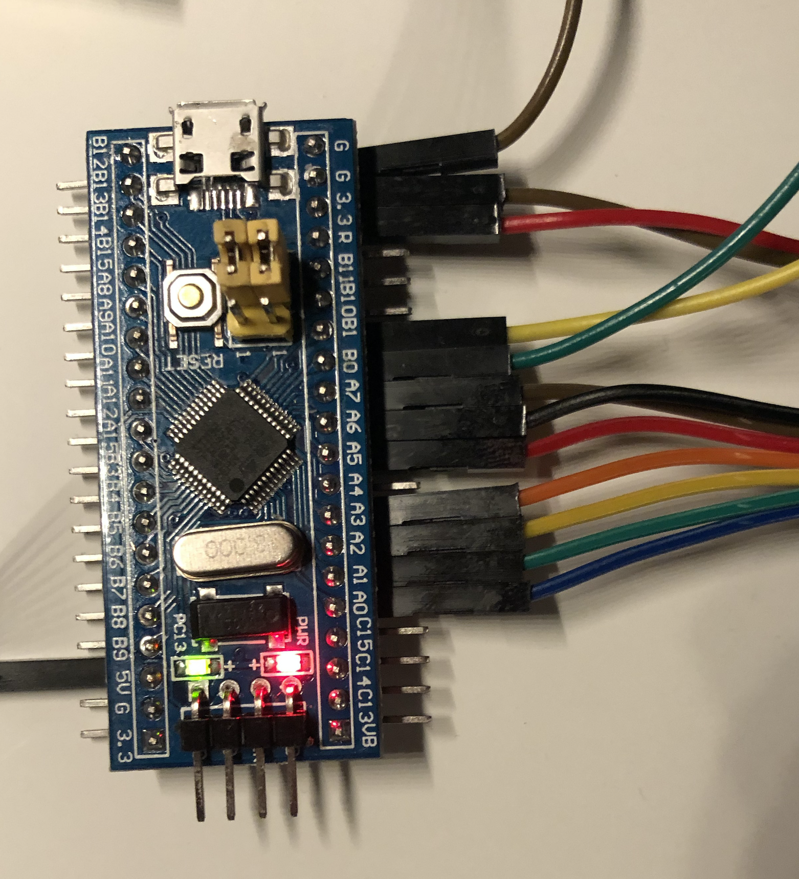

For prototyping, I used female-to-female jumper wires from this pack: Dupont line 120pcs 10cm male to male + male to female +female to female jumper wire Dupont cable for arduino, purchased for $3.51 (not included in the total price of this $10 o’scope). You could also use female-to-male jumper wires and a breadboard, or solder male-to-male wires, or use a custom printed circuit board, but F-F jumper wires are the most expedient for the initial prototype.
Compiling the software
The STM32-O-Scope software is an Arduino project. Flash the generic_boot20_pc13.bin bootloader using a USB-to-serial adapter onto the STM32F103 blue pill board. Then connect over USB and select the board and virtual serial port in the Arduino application, load up the pingumacpenguin/STM32-O-Scope sketch.
URTouch vs UTouch
Attempt to build but it fails:
STM32-O-Scope/STM32-O-Scope.ino:48:20: fatal error: UTouch.h: No such file or directory
 #include <UTouch.h>
                    ^
compilation terminated.
exit status 1
Error compiling for board Generic STM32F103C series.
The comments refer to the UTouch library but that page shows it was replaced by URTouch. Installed URTouch and replaced the code:
-// UTouch Library
-// http://www.rinkydinkelectronics.com/library.php?id=56
-#include <UTouch.h>
-UTouch  myTouch( PB12, PB13, PB14, PB15, PA8);
+// URTouch Library
+// http://www.rinkydinkelectronics.com/library.php?id=93
+#include <URTouch.h>
+URTouch  myTouch( PB12, PB13, PB14, PB15, PA8);
Made this change in pull request #5 UTouch has been replaced by URTouch. But there is another failure.
Time library conflict
After making the aforementioned fix, we have another problem:
stm32/STM32-O-Scope/STM32-O-Scope.ino: In function 'void showTime()':
STM32-O-Scope:598: error: 'hour' was not declared in this scope
     if (hour(tt) < 10) {
                ^
STM32-O-Scope:601: error: 'hour' was not declared in this scope
     TFT.print(hour(tt));
                      ^
STM32-O-Scope:603: error: 'minute' was not declared in this scope
     if (minute(tt) < 10) {
                  ^
STM32-O-Scope:606: error: 'minute' was not declared in this scope
     TFT.print(minute(tt));
                        ^
STM32-O-Scope:608: error: 'second' was not declared in this scope
     if (second(tt) < 10) {
                  ^
STM32-O-Scope:611: error: 'second' was not declared in this scope
     TFT.print(second(tt));
                        ^
STM32-O-Scope:613: error: 'day' was not declared in this scope
     TFT.print(day(tt));
                     ^
STM32-O-Scope:615: error: 'month' was not declared in this scope
     TFT.print(month(tt));
                       ^
STM32-O-Scope:617: error: 'year' was not declared in this scope
     TFT.print(year(tt));
                      ^
/Users/admin/rf/stm32/STM32-O-Scope/STM32-O-Scope.ino: In function 'void setCurrentTime()':
STM32-O-Scope:867: error: 'setTime' was not declared in this scope
   setTime(thisArg.toInt());
                          ^
STM32-O-Scope:868: error: 'getTime' was not declared in this scope
   time_t tt = now();
                   ^
/Users/admin/rf/stm32/STM32-O-Scope/STM32-O-Scope.ino: In function 'void serialCurrentTime()':
STM32-O-Scope:875: error: 'hour' was not declared in this scope
   if (hour(tt) < 10) {
              ^
STM32-O-Scope:878: error: 'hour' was not declared in this scope
   serial_debug.print(hour(tt));
                             ^
STM32-O-Scope:880: error: 'minute' was not declared in this scope
   if (minute(tt) < 10) {
                ^
STM32-O-Scope:883: error: 'minute' was not declared in this scope
   serial_debug.print(minute(tt));
                               ^
STM32-O-Scope:885: error: 'second' was not declared in this scope
   if (second(tt) < 10) {
                ^
STM32-O-Scope:888: error: 'second' was not declared in this scope
   serial_debug.print(second(tt));
                               ^
STM32-O-Scope:890: error: 'day' was not declared in this scope
   serial_debug.print(day(tt));
                            ^
STM32-O-Scope:892: error: 'month' was not declared in this scope
   serial_debug.print(month(tt));
                              ^
STM32-O-Scope:894: error: 'year' was not declared in this scope
   serial_debug.print(year(tt));
                             ^
exit status 1
'hour' was not declared in this scope
To fix this, had to make the following code changes:
--- a/STM32-O-Scope.ino
+++ b/STM32-O-Scope.ino
@@ -76,7 +76,7 @@ uint32 tt;
 #define  TOUCH_CALIB_Z 2

 // Time library - https://github.com/PaulStoffregen/Time
-#include "Time.h" //If you have issues with the default Time library change the name of this library to Time1 for example.
+#include "Time1.h" //If you have issues with the default Time library change the name of this library to Time1 for example.
 #define TZ    "UTC+1"

 // End RTC and NVRam initialization
@@ -865,7 +865,7 @@ void setCurrentTime() {
   serial_debug.print(thisArg.toInt() );
   serial_debug.println("]");
   setTime(thisArg.toInt());
-  time_t tt = now();
+  time_t tt = rt.getTime();
   rt.setTime(tt);
   serialCurrentTime();
 }
Committed locally in Fix time library conflict, rename to Time1 but didn’t pull request since it also requires a library file change. In Arduino/libraries, rename Time to Time1 and also Time/Time.h to Time1/Time1.h.
After all these changes, the software compiles and runs.
Trying it out with a test signal
Power up the ‘scope, and after a few seconds it boots, shows the splash screen, then the noise on the input probe (PB0):

Looks nice! To try it out, the STM32-O-Scope software includes a test signal on PB1, a square wave of approximately 500 Hz. Connect PB0 to PB1 and the square wave appears on the display as we expect:

The wiki recommends using a 1 MΩ resistor as an attentuator. I used a 1% 1/4 watt resistor (not included in the $10 price), measured 1.000 MΩ with a multimeter, in series with the PB0 input connecting to the PB1 test signal, and it was barely visible on the display. May be useful for measuring higher voltage signals, but not the test signal.
Touchscreen input
From the source code we see the additional wires for adding the optional touchscreen input. You can use an LCD screen without a touch panel, but I opted for one since it was only a couple more bucks. Now that the display works, time to hook it up, five more wires:
| STM32 blue pill board | ILI9341 LCD display board | Remarks |
|---|---|---|
| B12 | T_CLK | Touch clock |
| B13 | T_CS | Touch chip select |
| B14 | T_DIN | Touch data input |
| B15 | T_DO | Touch data output |
| A8 | T_IRQ | Touch interrupt request |
All of these pins are adjacent, but are on the other side of the blue pill board. I used right angle headers ($0.74 for 10pcs 40 Pin 1x40 Single Row Male 2.54mm Breakable Pin Header Right Angle Connector Strip bending, not included in the $10 price; also note panel module included pre-soldered striaght headers already). This leads to slightly awkward wiring, but it is passable:
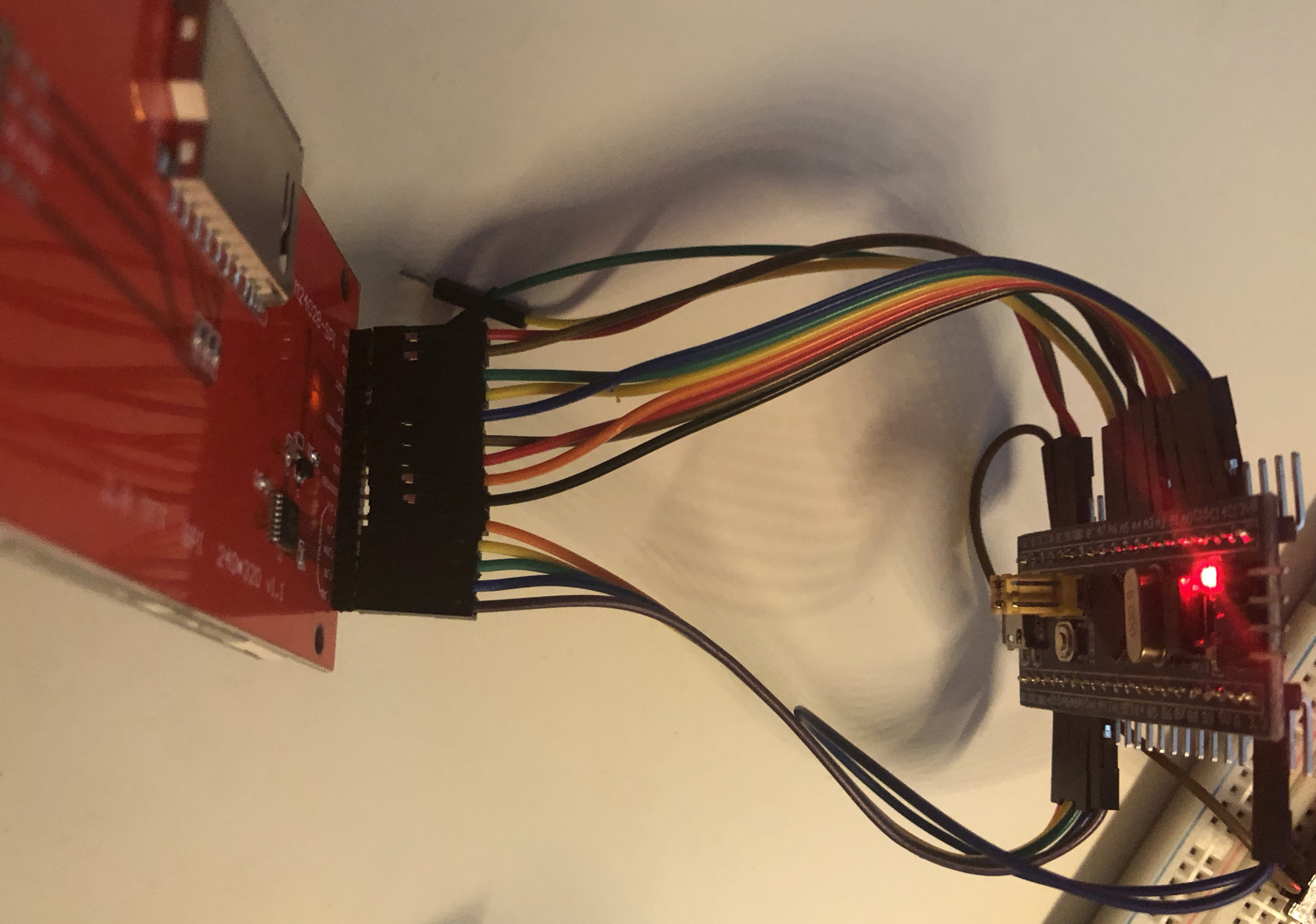
That’s a lot of wires. Peeled off the protective film, but touching the screen did nothing. Turns out it is disabled in the code, enable by removing this code:
// This makes no sense.. (BUG) but if you don't actually have a touch screen, #undef it here.
#undef TOUCH_SCREEN_AVAILABLE
Rebuild and reflash. Boots up and asks to press the dot to calibrate the screen. When I touch and hold it, concentric circles appear. Then touching the signal display draws red dots. Will have to learn about how this is meant to work exactly, but seems to be functioning.
SD card
This display module not only has an LCD and touch screen panel, but also an SD card slot, through an unpopulated header. 4 connections, also using SPI: SD_CS, SD_MOSI, SD_MISO, and SD_SCK. The LCD is connected to SPI1 (PA7/6/5/4), touch to SPI2 (PB12/13/14/15), could the SD card adapter connect to PA15/PB3/PB4/PB5?

Haven’t tried it because the STM32-O-Scope sketch doesn’t include support for the SD card, but could be an interesting project to investigate adding it. Storing the time series to the SD card? In the meantime, the STM32-O-Scope can already send data over serial to a PC for later analysis.
Conclusions
For the price, $10 + change (and a few spare parts I had lying around), when combined with the STM32-O-Scope softwrae we have seen it is possible to build an inexpensive yet usable oscilloscope. I’m not sure if I’ll use it for any serious projects, or should instead buy a “real” scope (Hackaday has a review of some slightly more expensive commercial oscilloscopes: A tale of two sub-$100 oscilloscopes), but we’ll see, at least it’s something.