blog
AT&T 1739 Digital Answering Machine teardown and resuscitation attempt
by snm, January 9th, 2018
Would you buy this for a dollar? Apparently no one did, so this Digital Answering System by at&t ended up like this:
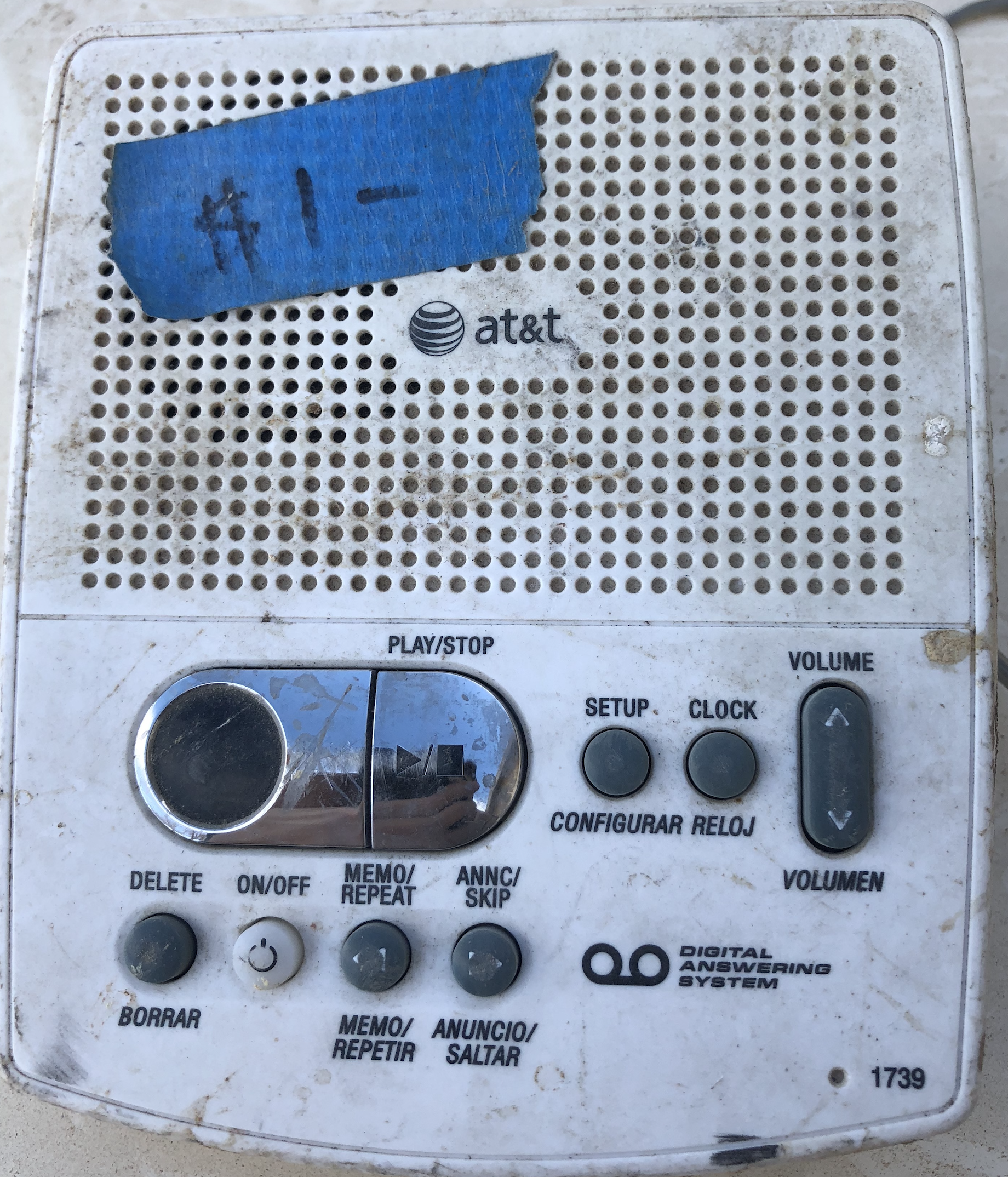
The front case consists of a grill for the speaker, and tactile buttons for play/stop, setup, clock, volume up/down, delete, on/off, memo/repeat, annc/skip, and the number 1739. The reverse side of the case is even filthier, can’t make out the compliance notices, can barely read the instructions “To set the clock: press and hold [CLOCK] until you hear the day of the week. To change day/hour/minutes and year: use [MEMO/REPEAT] and [ANNC/SKIP]. Press [CLOCK] after each is set:”

Model 1739, SN E5??3804887. I found the manual here: AT&T 1739 User Manual. Yes, that’s it:

This is how you’re supposed to hook it up:

The power input is 6VAC, 350 mA…crucially, AC not DC. Didn’t get a wall adapter with it. Assuming 120VAC input, 6VAC would be a 20:1 step-down. Absent a compatible power supply, I decided to take it apart.
Opening it up
Ripping out its guts, the circuitry is in pristine shape, betraying its outside condition:

The silkscreen reads KR_DS_DS-1107A and 35-007381-001-100 >PF-LP<, major visible components include the speaker (8 Ω, 0.4 W), microphone, modular telephone jack, barrel-style power connector, two large electrolytic capacitors (both 4700 µF 16V), 3.579545/0B crystal, a header in the corner labeled “T&R” for tip and ring (it connected to a modular telephone connector plug) and a moderate number of other discrete components. Flipping it over, we see a 7-segment LED display, a couple of chips, and an epoxyed “glob top” semiconductor module where the magic happens:

Undoubtedly a proprietary application-specific integrated circuit. Taking a closer look, we see the silkscreen text “BS COB(MASK)” on the printed circuit board on top of the module, and “35-006657-001-100” beneath it:

Moving in closer, on the epoxy itself, “30664-OP-100 B98/C B43/D/C/A-10 06/05/10”:

All I can make out from this label is the date code, appears to be June 5th, 2010. This seems about right, despite being part of the aging Plain old telephone service (POTS) system, this is a relatively modern device. Unlike answering machines of yore, there is no tape. Where are the messages stored? I’d wager in flash memory (or even RAM?), in the glob top. Found it on Amazon: AT&T 1739 Corded Digital Answering System, White, for sale for $9.60, and reviews as latest as two years ago:
Mochni (Talking Bird) 2.0 out of 5 stars
Handy, up to a point, but not as advertised.
June 6, 2016 Verified Purchase
OK, except it loses all messages when power goes out, despite the product description. I have never had a memory-featured item “wear out” like this one.
Presumably superseded by the 1740 model, sold on telephones.att.com for $17.95: Digital Answering System with Time/Day Stamp, but it doesn’t look much different.
Powering it up
How can we get 6VAC? Well, I got a line transformer which ouptuts 21VAC and 10.5VAC from the Kinyo 1-way VHS Rewinder UV-428 teardown. Stepping down these to 6VAC could be done with a 3.5:1 or 1.75:1 ratio transformer. It’s a start, I’ll use the ~6:1 line transformer first, to work with a safer voltage, then try to step it down further. Desolder the DC motor which was wired to the rectifier board’s output, leaving us with the AC wall plug connected to the transformer (red wires), the stepped-down AC output and rectifier board:

Adding a power indicator LED to the Kinyo supply
It would be handy to have an indicator when this power supply is energized, so I soldered a yellow LED to the DC output, in series wiht a current-limiting resistor. At about 13 VDC output, minus about 1.8 V drop across the LED, divided by 20 milliamperes maximum, computes to a 560 Ω resistor. Picked the next closest, a 680 Ω, which will limit the current slightly more. Soldered it up, minding the LED polarity, now we have a simple power indicator to see when it is on:

The capacitor stores charge, so the LED slowly dims when the power is removed, takes about a second. Note, I used a 1/4 watt resistor, but this is probably too low, the resistor becomes noticeably warm. Use a higher-wattage resistor if the circuit needs to be powered for extended periods of time, or better yet, step down or buck the voltage to a more appropriate level. But for now, this’ll do.
Stepping down to 6 VAC with a variac
Why does this answering machine need AC, anyways? It feeds the input voltage, across a spark gap, directly into a 4-diode full-wave bridge rectifier. Much of the circuit is DC, but it may still use AC for some purpose.
Searching found a post, AC output plugpack design needed, someone in a similar situation needing to replace a 6VAC power adapter (but for a sentimental lamp, not a junk answering machine), and this transformer was suggested: M7252 • 10VA 6+6V PCB Transformer. At $16.50 I’ll pass, but it looks like it would work.
Is it possible to lower AC voltage without a transformer?. Wendy replied “Sure, you can use a low ohmage resistor, a coil, or a capacitor in series, depending on the load.” Triac dimmers are another option. Another thread suggests using a resistive voltage divider. But what would be most immediately testable is a transformer where we could adjust the ratio to get the right voltage, this exists and is known as a variac or variable autotransformer.
Wire up the 21 VAC output across the coil of the variac, then take the stepped-down voltage one side of the coil, as well as the knob, wiring this output to the answering machine’s barrel connector power input. The complete contraption:

The moment of truth…
Success, then failure
When I first powered it up, a click was heard from the speaker the “answering” LED started blinking! It seemed to be working!
But then I powered it off, and back on, and only the speaker clicking remained. No more blinking answering LED. Instead, the 7-segment display briefly turned on, then slowly off. Best picture I could capture of this phenomena:

What happened? My best guess is we just witnessed the downside of unregulated power supplies. When the makeshift 6 VAC power supply is plugged in, the output voltage, as measured by multimeter, spikes to overload, before the scale adjusts to the expected value. Inrush current? Furthermore, there are no regulators anywhere in this supply. The voltage comes in from the mains, then is stepped down from a fixed ratio, and then from a variable ratio, but there is no circuitry to ensure the voltage never exceeds a maximum threshold or drops below a minimum. Whatever comes out of the wall, divided down, is what the answering machine circuitry will get.
Tried fiddling with the variac adjustment, tried turning it off and on again, but try as I might, nothing seemed to resucitate this answering machine. Was a component fried? The fuse, at least, was still good. Couldn’t get it to work. Oh well, had to give up. At least it briefly may have worked. Next time, maybe make a regulated AC power supply.
Since I considered it dead, next I figured I’d increase the voltage and see what happens. Seeing as it appears to briefly turn “on” when first plugged in, assuming a voltage spike. At 21 VAC, the speaker makes a constant clicking noise, and the 7-segment display illuminates all the segments. No blinking answering LED, in any case. Not sure what is going on here, but it is time to write it off.
Tearing to pieces
All that is left now to do is pick away at the parts, taking what can possibly be useful elsewhere. Not much to this board, but here is what I desoldered, at least for the time being:

- 2 x 4700 µF 16V electrolytic capacitors, and one 1000 µF
- Speaker, 8Ω 1/4W
- Microphone
- Barrel jack connector
- Modular telephone connector
- Fuse
- LED, red, clear
- 7-segment LED display
- Crystal, “3.579545/0B”
The LEDs still work (both the 7-segment and singular LED), the fuse seems still good not measuring an open, the speaker measures about 8Ω, so all the parts I tested seemed fine, except I couldn’t get the crystal to oscillate for unknown reasons.