blog
STM32 Blue Pill ARM development board first look: from Arduino to bare metal programming
by snm, December 12th, 2017
Inspired by the The Amazing $1 Microcontroller - Jay Carlson, I purchased a STM32 microcontroller. Specifically, the STM32F103C8T6 ARM STM32 Minimum System Development Board Module Forarduino board from Aliexpress for $1.85 (not bad for the full development board).
This is actually a different chip than Jay Carlson covered, ST Micro’s STM32 32-bit microcontroller product lineup ranges from the low-end STM32F0 featuring an ARM Cortex-M0 up to the STM32F7 with a Cortex-M7F:
Next up, the STM32 line. The STM32F0 has a famous big brother — the STM32F4 — that’s one of the most capable Arm Cortex parts ever built. Several versions run up to 180 MHz, with 2 MB of flash and up to 364 KB of RAM (in the case of the STM32F469).
But the brand-new STM32F7 — part of the new Cortex-M7 line of parts — goes even further, with 216 MHz maximum operating frequency, 2 MB of flash, and 512 KB of RAM.
The STM32F4 seems to be one of the most popular, it even has its own subreddit /r/stm32f4. Could’ve gotten one of those or the cheapest ‘F0 but the ‘F1 kit was inexpensive and I decided to go for it instead. From Wikipedia, the 103 model (STM32F103) is focused on performance:
The STM32 F1-series was the first group of STM32 microcontrollers based on the ARM Cortex-M3 core and considered their mainstream ARM microcontrollers. The F1-series has evolved over time by increasing CPU speed, size of internal memory, variety of peripherals. There are five F1 lines: Connectivity (STM32F105/107), Performance (STM32F103), USB Access (STM32F102), Access (STM32F101), Value (STM32F100).
Cool. This is a 72 MHz processor. The full part number STM32F103C8T6 decodes to C8 = 128 KB flash, 20 KB RAM, 48-pin LQFP:

What is the T6 in STM32F103C8T6? Digikey has 6 matches for STM32F103C8, so T6 appears to indicate the packaging; not important for programming specifications.
Software
I’d like to run RetroBSD, but it targets the Microchip PIC32 microcontroller (128 KB RAM, 512 KB flash), maybe it can be ported to the STM32F1? There is some discussion on the RetroBSD forums: STM32F103ZET6 board for RetroBSD?.
How about Arduino? Found this useful page: Sunspot: Experiments with the Arduno IDE connected to a generic ARM board - containing an STM32F103C8T6, which points to [https://github.com/rogerclarkmelbourne/Arduino_STM32)(https://github.com/rogerclarkmelbourne/Arduino_STM32) described as “Arduino STM32. Hardware files to support STM32 boards, on Arduino IDE 1.8.x including LeafLabs Maple and other generic STM32F103 boards”. There is an active community and support forum at http://www.stm32duino.com.
The device I ordered looks a lot like the what they call a “Blue Pill”. An important caveat from that page:
Please note. This board will not be usable when you receive it, as it does not contain a bootloader.
stm32duino’s wiki page for Blue Pill has more information. The Maple mini clones don’t require flashing a bootloader. What do I have? Let’s try just plugging in the micro USB and powering it:

The red power LED turns on solid, and the green PC13 LED blinks continuously. No serial port shows up in /dev/. This is because you must burn the bootloader.
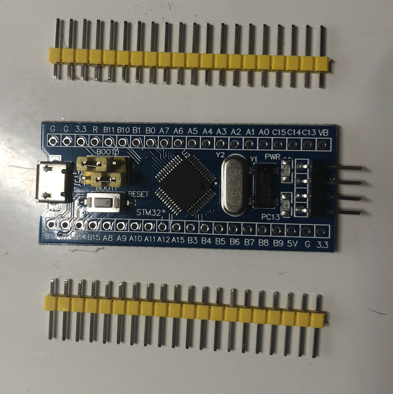
Headers
Solder on the provided headers. This took longer than expected, due to a n00b mistake of not orienting the header straight and nonetheless soldering all the pins; had to desolder with copious amounts of flux:

and clean it up then reorient correctly, but all’s well that ends well:

Bootloader
Follow the instructions in Burning the bootloader. When I set boot0 to 1 high and boot1 to 0 low, when powered only the power LED illuminates. Now to connect the serial. Stm32duino gives instructions for the newer “black pill” board, connecting RX to PA9 and TX to PA10, where are these pins? Spotspot gives a hint: they are PA9 and PA10 are labeled A9 and A10 on the board. Let’s do this. Wire up TX, RX, GND, and 3V3 to a USB-to-serial adapter:

The instructions for flashing the bootloader are for Windows or Linux, but I’m on macOS, so I found this to try instead: stm32loader. It appears to detect the STM32 correctly:
stm32loader $ python stm32loader.py -p /dev/tty.usbserial-*
Bootloader version 22
Chip id: 0x410 (STM32 Medium-density)
But now the link on the wiki to generic_boot20_pb12.bin is broken: https://github.com/rogerclarkmelbourne/STM32duino-bootloader/raw/master/STM32F1/binaries/generic_boot20_pb12.bin. Poking around, found it here: https://github.com/rogerclarkmelbourne/STM32duino-bootloader/blob/master/binaries/generic_boot20_pb12.bin - flash it:
stm32loader $ python stm32loader.py -p /dev/tty.usbserial-* -e -w -v  ../generic_boot20_pb12.bin
Can't init. Ensure that BOOT0 is enabled and reset device
Bootloader version 22
Chip id: 0x410 (STM32 Medium-density)
Write 256 bytes at 0x8000000
...
Read 256 bytes at 0x8005200
Verification OK
Progress. Change boot0 back to 0, then plug in to a PC using the micro USB port. Now it shows up as: /dev/cu.usbmodem1421. Connect using GNU screen:
screen -L /dev/cu.usbmodem* 115200

Congratulations, you have installed the STM32duino bootloader
See https://github.com/rogerclarkmelbourne/STM32duino-bootloader


For more information about Arduino on STM32
and http://www.stm32duino.com
Sweet. It keeps repeating this message, looks like it worked. Now to fire up the old trusty Arduino app.
Arduino_STM32
Install Arduino_STM32 as described on https://github.com/rogerclarkmelbourne/Arduino_STM32/wiki/Installation. Make sure to install the Arduino Zero board to get the compiler, which the board manager called “Arduino SAMD Boards”. Restart and the STM32 boards appear (unlike Sunspot, I didn’t need to add the hardware libraries to the Arduino.app bundle itself). What is the supported hardware of Arduino_STM32? “Virtually any STM32F103C8x or STM32F103CBx board”, that’s what I have, a STM32F103C8T6. Select “Generic STM32F103C Series”, then load an example: File > Examples > A_STM32_Examples > General > Blink, try to compile and upload… but it fails:
Sketch uses 13092 bytes (19%) of program storage space. Maximum is 65536 bytes.
Global variables use 2816 bytes (13%) of dynamic memory, leaving 17664 bytes for local variables. Maximum is 20480 bytes.
Failed to open serial device.
dyld: Library not loaded: /opt/local/lib/libusb-1.0.0.dylib
Referenced from: Arduino/hardware/Arduino_STM32/tools/macosx/dfu-util/dfu-util
Reason: image not found Arduino/hardware/Arduino_STM32/tools/macosx/maple_upload: line 53: 12945 Abort trap: 6 ${DFU_UTIL} -d ${usbID} -a ${altID} -D ${binfile} -R ${dfuse_addr} -R
An error occurred while uploading the sketch
That’s not good. Running /Arduino/hardware/Arduino_STM32/tools/macosx/dfu-util/dfu-util manually confirms the error: it is missing libusb. Found an open issue: #256 macOS: libusb is not included, that dfu-util depends on.
Install Homebrew then run brew install libusb. This installs libusb but in /usr/local/Cellar, symlink it into /opt:
brew install libusb
sudo mkdir -p /opt/local/lib
sudo ln -s /usr/local/Cellar/libusb/1.0.21/lib/libusb-1.0.0.dylib /opt/local/lib/libusb-1.0.0.dylib
dfu-util now runs without error:
dfu-util $ ./dfu-util
dfu-util 0.8

Copyright 2005-2009 Weston Schmidt, Harald Welte and OpenMoko Inc.
Copyright 2010-2014 Tormod Volden and Stefan Schmidt
This program is Free Software and has ABSOLUTELY NO WARRANTY
Please report bugs to http://sourceforge.net/p/dfu-util/tickets/

You need to specify one of -D or -U
Usage: dfu-util [options] ...
but Arduino.app still struggles uploading:
Sketch uses 13092 bytes (19%) of program storage space. Maximum is 65536 bytes.
Global variables use 2816 bytes (13%) of dynamic memory, leaving 17664 bytes for local variables. Maximum is 20480 bytes.
dfu-util 0.8

dfu-util: Invalid DFU suffix signature
Copyright 2005-2009 Weston Schmidt, Harald Welte and OpenMoko Inc.
dfu-util: A valid DFU suffix will be required in a future dfu-util release!!!
Copyright 2010-2014 Tormod Volden and Stefan Schmidt
This program is Free Software and has ABSOLUTELY NO WARRANTY
Please report bugs to http://sourceforge.net/p/dfu-util/tickets/

dfu-util: No DFU capable USB device available
An error occurred while uploading the sketch
What’s wrong with my capable device? There is an open issue on their tracker: #328 No DFU capable USB device available. ./dfu-util --list finds a device:
Found Runtime: [05ac:8296] ver=0061, devnum=4, cfg=1, intf=5, alt=0, name="UNKNOWN", serial="UNKNOWN"
The Arduino app is invoking dfu-util like this:
Arduino/hardware/Arduino_STM32/tools/macosx/dfu-util/dfu-util -d 1EAF:0003 -a 2 -D /var/folders/81/3xnrrjrn3hzd1sks0yvxwp1w0000gn/T/arduino_build_216855/Blink.ino.bin -R -R
Curious, where did it get device 1EAF:0003? My device as shown by –list is 05ac:8296. If I rerun dfu-util with the correct device identifier, it gets further:
$ Arduino/hardware/Arduino_STM32/tools/macosx/dfu-util/dfu-util -d 05ac:8296 -a 2 -D /var/folders/81/3xnrrjrn3hzd1sks0yvxwp1w0000gn/T/arduino_build_216855/Blink.ino.bin -R -R
dfu-util 0.8

Copyright 2005-2009 Weston Schmidt, Harald Welte and OpenMoko Inc.
Copyright 2010-2014 Tormod Volden and Stefan Schmidt
This program is Free Software and has ABSOLUTELY NO WARRANTY
Please report bugs to http://sourceforge.net/p/dfu-util/tickets/

dfu-util: Invalid DFU suffix signature
dfu-util: A valid DFU suffix will be required in a future dfu-util release!!!
Opening DFU capable USB device...
ID 05ac:8296
Run-time device DFU version 0110
Claiming USB DFU Runtime Interface...
Determining device status: state = appIDLE, status = 0
Device really in Runtime Mode, send DFU detach request...
Resetting USB...
dfu-util: Lost device after RESET?
$
So did it work? No blinking LED, maybe wrong output? Try the HelloWorld example, serial monitor, but it still only repeats the “Congratulations, you have installed the STM32duino bootloader” message in a loop, not the hello world.
Hmm, Get Board Info shows VID: 1EAF, PID: 0004, not 05ac:8296. What is this device really? Installing lsusb for Mac from https://github.com/jlhonora/lsusb reveals it is the Bluetooth controller! It isn’t anything related to the STM32. 1eaf:0004 (see, it spells out “leaf”) is correct:
$ lsusb
Bus 020 Device 004: ID 05ac:8296 Apple Inc. Bluetooth USB Host Controller
Bus 020 Device 008: ID 05ac:8511 Apple Inc. FaceTime HD Camera (Built-in)
Bus 020 Device 009: ID 1eaf:0004 1eaf Maple
Bus 000 Device 001: ID 1d6b:ISPT Linux Foundation USB 3.0 Bus
Bus 000 Device 001: ID 1d6b:CIAR Linux Foundation USB 3.1 Bus
not 1EAF:0003, but it’s close. Off by one. What is going on? boards.txt shows the product IDs are 0x0004, but the upload USB IDs all end in 0x0003 instead. Are there two devices? Yes: if I run lsusb in a loop, while plugging in the STM32 board, then it briefly finds the 1eaf:0003 device:
Bus 020 Device 020: ID 1eaf:0003 1eaf Maple 003 Serial: LLM 003
then soon after it disappears and only the other device shows up:
Bus 020 Device 021: ID 1eaf:0004 1eaf Maple
This jives with what the developer says about the system not enumerating the USB devices fast enough. Found this open pull request: #14 Fixed timing for Mac enumeration and added a variant.
Reflashing the bootloader
The diffs include a binary STM32F1/binaries/generic_boot20_pc13.bin (hmm, is PC13 = the LED?). I already flashed generic_boot20_pb12.bin but going to try this other fixed bootloader. Wire up a USB-to-serial adapter again as before (RX to A9 and TX to A10, 3V3 to +3V and GND to ground), change boot0 to 1. Reflash:
stm32loader $ python stm32loader.py -p /dev/tty.usbserial-* -e -w -v ../generic_boot20_pc13-pr14.bin
Change the boot0 jumper back to 0 (both are 0), then connect the micro USB port. This looks better! The red power LED is on as before, but now the green LED (PC13) blinks continously. And lsusb for Mac shows the 0003 device:
Bus 020 Device 024: ID 1eaf:0003 1eaf Maple 003 Serial: LLM 003
Try uploading a sketch, much better:
Sketch uses 13004 bytes (11%) of program storage space. Maximum is 110592 bytes.
Global variables use 2816 bytes (16%) of dynamic memory, leaving 14592 bytes for local variables. Maximum is 17408 bytes.
Failed to open serial device.
dfu-util: Invalid DFU suffix signature
dfu-util: A valid DFU suffix will be required in a future dfu-util release!!!

dfu-util 0.8

Copyright 2005-2009 Weston Schmidt, Harald Welte and OpenMoko Inc.
Copyright 2010-2014 Tormod Volden and Stefan Schmidt
This program is Free Software and has ABSOLUTELY NO WARRANTY
Please report bugs to http://sourceforge.net/p/dfu-util/tickets/

Opening DFU capable USB device...
ID 1eaf:0003
Run-time device DFU version 0110
Claiming USB DFU Interface...
Setting Alternate Setting #1 ...
Determining device status: state = dfuIDLE, status = 0
dfuIDLE, continuing
DFU mode device DFU version 0110
Device returned transfer size 1024
Copying data from PC to DFU device

Download	[                         ]   0%            0 bytes
Download	[=                        ]   7%         1024 bytes
Download	[===                      ]  14%         2048 bytes
Download	[=====                    ]  21%         3072 bytes
Download	[=======                  ]  29%         4096 bytes
Download	[=========                ]  36%         5120 bytes
Download	[==========               ]  43%         6144 bytes
Download	[============             ]  51%         7168 bytes
Download	[==============           ]  58%         8192 bytes
Download	[================         ]  65%         9216 bytes
Download	[==================       ]  72%        10240 bytes
Download	[====================     ]  80%        11264 bytes
Download	[=====================    ]  87%        12288 bytes
Download	[=======================  ]  94%        13004 bytes
Download	[=========================] 100%        13004 bytes
Download done.
state(8)
finally able to upload the Blink example, and the LED blinks once per second, as programmed.
Project ideas
Now what? There’s a bunch of Arduino libraries available for the STM32F1. Although not all may be necessarily fully functional. There is a commit today to port the Adafruit_SSD1306 library, but with a disclaimer it only compiles and may not function. If it did, we could use the other display covered in Monochrome 2.7” and 2.42” 128x64 OLED displays on a Raspberry Pi Zero.
There’s a respectable number of I/O ports on this chip and board. Thanks to the stm32duino wiki, here is the pinout for the generic blue pill:

There are the interfaces you would expect: I2C, SPI, GPIO, etc. But also CAN, the Controller Area Network, used in onboard diagnostics (OBD) of cars. No project ideas for CAN, however. There are 10 analog input channels (ADC), and plenty of timers and pulse-width modulation (PWM) output pins. Could be useful for a project with lots of analog (or digital) inputs or outputs.
But without wireless, as featured in the ESP8266 or ESP32 which have built-in Wi-Fi, its application is limited without external networking hardware, it may not be the best choice for Internet of Things development. But it is very low power, with a USB safety tester I measure <100 mA when powered on.
TODO: do something useful with it
TODO: maybe a controller for a laptop? Laptops often have a separate microcontroller for various power mangement purposes. Built one initially in Custom laptop upgrades: internal breadboard, power indicator, and larger case, then improved in Building a small custom Raspberry Pi Zero laptop in a cardboard box, how about adding a micro to monitor and control the laptop out-of-band from the main Pi Zero processor?
USB, or not
The STM32F103, unlike other popular microcontrollers like the ESP8266 or ESP32 (which are often paired with a separate USB-to-serial adapter), features onboard USB. How about some useful USB projects? Harprasad’s STM32F103 USB Tutorial looks like a good place to start, using ST’s USB_FS_Library_4.0 library through the CooCox CoIDE for Windows. Then there’s also arpruss/KeyboardMouse_stm32f1, a USB keyboard and mouse library for the STM32F1, released yesterday. But these are both for USB device mode, where the microcontroller acts as a device, such as a mouse or keyboard.
How about USB host mode? emcu’s USB on-the-go Host and Device for STM32F105/7xx, STM32F2xx and STM32F4xx looks quite nice, and complete:
The STM32F105/7xx, STM32F2xx and STM32F4xx USB On-The-Go provides a free and complete firmware package that makes implementation of Host and Device interfaces in STM32 applications quick and easy. Fully compliant with the Universal Serial Bus Revision 2.0 Specification.
but it is only for these boards and processors:
- STM3210C-EVAL evaluation board (UM0600) for STM32F105/7 devices
- STM3220G-EVAL evaluation board (UM1057) for STM32F20x devices
- STM3221G-EVAL evaluation board (UM1065) for STM32F21x devices
- STM3240G-EVAL evaluation board (UM1461) for STM32F40x devices
- STM3241G-EVAL evaluation board (UM1460) for STM32F41x devices
The ‘105 and ‘107 are listed, but the ‘103 I have is notably absent. What gives? ST’s own STM32F1 Series webpage has the answer:

STM32F103 has USB 2.0 full speed, but only the more expensive STM32F105 and STM32F107 ($20-30, versus $3.50 or cheaper) have USB On-The-Go, to allow USB devices to connect to it as a host.
The Raspberry Pi Zero for comparison has USB OTG mode, supported through a micro USB to USB-A female OTG cable, but it also supports device mode using the Linux-USB Gadget API framework. The Raspberry Pi 3 only supports USB host mode, and the STM32F103 only device mode. To summarize:
| Device | USB host mode | USB device mode |
|---|---|---|
| STM32F103 | ✔ | |
| STM32F105/7 | ✔ | ✔ |
| ESP8266/32 | ||
| Raspberry Pi Zero | ✔ | ✔ |
| Raspberry Pi 3 | ✔ |
The STM32F103 could therefore be useful as the brains of some kind of a device to plug into your computer. The SiFive folks found this chip suitable to use as a USB-to-serial converter (providing a virtual serial port device over USB), in Arduino Cinque – the RISC-V, ESP32, WiFi, Bluetooth Arduino. An alternative to purpose-built serial-USB chips like the FT232 or SiLabs CP2102, common in inexpensive ESP8266 boards. But the STM32F103 as a general-purpose microcontroller may be more flexible. There are plenty of device classes supported by USB, this chip could become nearly any of them.
How about showing up as a USB keyboard, with programmable keystrokes from a USB mass storage device? Not terribly interesting, the USB Rubber Ducky can already do this, albeit at a steep $44.99 price tag. At $1.85 a hypothetical STM32F103-based comparable device would be less than 4% of the cost, if it could be done.
But going back to the USB-to-serial conversion concept, how about generalizing it to USB-to-anything? Or to most of its interfaces. The infamous Bus Pirate v3.6 uses a PIC24 and an FT232RL to allow connecting over USB (as a virtual serial port) host computer, to debug and test peripherals with many protocols including I2C, SPI, JTAG, UART, and more. Sparkfun sells the Bus Pirate v3.6a for $30. The STM32F103 has some possibly interesting interfaces for experimentation, such as the CAN bus used on controllers in automobiles (see: CAN Bus Library for STM32F103). Comparing the chips:
| Bus Pirate v4.0 | Bus Pirate v3.6a) | Blue Pill dev board | |
|---|---|---|---|
| Price | $37.15 @ Seeed | $27.15 @ Seeed | $1.85 @ Aliexpress |
| Microcontroller | Microchip PIC24FJ256GB106 | Microchip PIC24FJ64GA002 | STM32F103C8T6 |
| Micro price | $5.43/1 @ Microchip | $2.83/1 @ Microchip | $2.056/1000 @ ST (> than the Blue Pill board!) |
| CPU series | PIC24 | PIC24 | ARM Cortex-M3 |
| CPU speed | 8 MHz | 8 MHz | 72 MHz |
| Flash memory | 256 K | 64 K | 128 K (or 64 K) |
| SRAM memory | 16 K | 8 K | 20 K |
| USB | builtin to PIC24, host/OTG or device | FTDI FT232RL | builtin to STM32F103, device only |
| I/O pins | 7 (6x2 header) | 5 (5x2 header) | 37 I/Os |
| Digital peripherals | 4-UART, 3-SPI, 3-I2C | 2-UART, 2-SPI, 2-I2C | 3-USART, 2-SPI (18 Mbit/s), 2-I2C, CAN bus (2.0B) |
| Analog peripherals | 1-A/D 16x10-bit @ 500ksp | 1-A/D 10x10-bit @ 500ksp | 2-A/D, 16x12-bit, 1 µS 0-3.6V |
This board is looking quite competitive, at least given the technical specs vs price point. But the Bus Pirates are complete products, preloaded with solid battle-tested firmware; a hypothetical competitor based on the “Blue Pill” STM32F103C8T6 ARM STM32 Minimum System Development Board Module doesn’t exist yet. Is it possible?
Bare metal
Although is it immensely popular, Arduino has some detractors who prefer to develop closer to the metal. Bare metal.

What does this mean? Or what exactly is “Arduino”? Several things, per Wikipedia:
Arduino is an open source computer hardware and software company, project, and user community that designs and manufactures single-board microcontrollers and microcontroller kits
The company is at https://www.arduino.cc, where you can download the Arduino IDE (Arduino.app). But it’s grown far beyond them. Originally only for their own boards, including their “Genuino” trademark brand boards, independent developers from around the world have extended the platform for countless other boards, including the ESP8266 I previously used in The smart bulb / smart switch dilemma: smartening up a dumb wall switch, and the STM32 in the previous section whose Arduino_STM32 was made by rogerclarkmelbourne of stm32duino. These all have the commonality that you can use the Arduino IDE, and program in C++ using most of the Arduino API, famous for e.g. digitalRead() and similar functions. Code can be written and portable across multiple microcontrollers, thanks to Arduino as an abstraction layer, indirectly accessing the hardware, hiding its persnickety details.
“All problems in computer science can be solved by another level of indirection” -David Wheeler
This makes it easy, and Arduino has a large and active user community, but indirection comes at a cost. Generally, less control and performance. But what specifically? Informative thread at EEVblog forums: Arduino vs. “Bare Metal” programming, a few choice quotes:
… It’s not just the bootloader, it’s the libraries too. Timing would be an example where the Arduino environment can screw you over.
… “bare metal” as you call it simply means talking directly to the hardware registers yourself, rather than using library routines to do so. The advantages are eliminating the sometimes huge performance overhead of the libraries and having full control over what happens.
… The main advantage of eliminating the bootloader is that you now have the entire flash memory space for your program. The big disadvantage is that you lose the ability program the avr over the serial interface. You’ll have to program via the ISP header instead.
… It’s not a huge hassle to program via the ISP. It needs some minor figuring out, but then it’s fairly straightforward. I think I actually prefer it, because it makes the board super simple.
What is ISP? No not Internet Service Provider. In-system programming, aka in-circuit serial programming (ICSP). You may have seen ICSP headers on various electronic devices, including retail production boards. Requires a programmer, the PICkit is one such programmer, for Microchip’s PIC microcontrollers, and there are clones for Atmel’s AVR microcontrollers too. Atmel has their own Atmel Studio. But we’re getting too far off track. How can we program the STM32 bare metal? STMicroelectronics provides the STM32 Open Development Environment, containing:
STM32Cube
STM32Cube software. A set of free-of-charge tools and embedded software bricks to enable fast and easy development on the STM32, including a Hardware Abstraction Layer, middleware and the STM32CubeMX PC-based configurator and code generator
Download the STM32CubeF1. It requires a valid email, then they email you a link to download. After jumping through these hoops, I ended up with:
- en.stm32cubemx.zip (387.4 MB)
- en.stm32cubef1.zip (102.0 MB)
Unzip the STM32CubeMX archive, and see it contains binaries for three platforms: macOS, Windows, and Linux. Run the Mac installer, SetupSTM32CubeMX-4.23.0.app. It wouldn’t show up when I double-clicked, so I ran it from the command-line since it is written in Java:
en.stm32cubemx $ ./SetupSTM32CubeMX-4.23.0.app/Contents/MacOs/SetupSTM32CubeMX-4_23_0_macos
Dec 9, 2017 7:50:47 PM INFO: Logging initialized at level 'INFO'
Dec 9, 2017 7:50:47 PM INFO: Commandline arguments:
Dec 9, 2017 7:50:47 PM INFO: Detected platform: mac_osx,version=10.13.2,arch=x86,symbolicName=null,javaVersion=1.8.0_131
Dec 9, 2017 7:50:49 PM WARNING: Cannot write to '/usr/share/applications'

This is already a lot more powerful than Arduino, but I’m powering through. Step through the installation steps, installed to /Applications/STMicroelectronics/STM32CubeMX.app, launch the app and it presents this window:

It feels non-native, no menu bar at the top of the screen, and the menus in the window open noticeably slowly. Not as intuitive as Arduino, which opens with a code sample template project. Bearing with me, I click New Project, then it downloads some files, takes a while. Finally getting somewhere, the app lists the MCU (microcontroller) selector and Board Selector, and my STM32F103C8 is there (the chip in the blue pill on Aliexpress):

Start project. I’m presented with a pinout diagram of the microcontroller, looks like you can select what integrated peripherals to activate here. Will need to read up and/or watch videos to see how to continue further, learning this new development environment. It’s for a different microcontroller series, the STM32L (L = low power), but I’ve always enjoyed Dave Jone’s EEVblog videos, he has one here: EEVblog #900 - STM32 ARM Development Board. Long story short, the STM32Cube software is for configuring the board initialization, using an easy-to-use GUI instead of obscure register twiddling code buried deep in a data sheet. It’s a code generator, generating initial configuration code for various toolchains. Using this tool isn’t strictly necessary, but initialization code is necessary. It can generate code for multiple toolchains.
Which toolchain to use? Project > Generate Code > Toolchain / IDE gives several options:
IDE evaluation

- EWARM
- MDK-ARM V4
- MDK-ARM V5
- TrueSTUDIO
- SW4STM32
- Makefile
- Other toolchains (GPDSC)
EEVblog seems to want GCC but it isn’t listed here. How about just Makefile? Plain old school Unix, I like it. EEVblog however starts with EWARM, the Embedded Workbench for ARM from IAR, they have free trials on their site. 30-day time-limited, or 32 KB size-limited trials. Ugh, who wants limitations? Full support requires purchasing a license. How is this better than Arduino again? The YouTube comments suggest using TrueSTUDIO from Atollic, a free download which has GCC, but it only had Windows and Linux installers, no Mac. How about IDEs for the STM32F103C8? Check the STM32F103C8 product page, scroll down to “Software Development Tools”, there are more options:
- CooCox CoIDE, a free and highly-integrated software development environment for ARM Cortex MCUs
- Cosmic ARM/Cortex “M” Cross Development Tools for STM32 Microcontroller
- Rowley Associates CrossWorks, integrated development environment with JTAG Flash download and debug
- ARM Development Studio 5 (DS-5) provides best-in-class tools for the broadest range of ARM processor-based platforms
- Emprog ThunderBench, fully integrated and well-crafted development C/C++ tools for ARM Cortex
- iSYSTEM’s free unlimited software development platform for all STM32 Cortex-M based devices
- MDK-ARM software development environment for Cortex-M based MCUs (Keil)
- MikroElektronika full-featured Basic compiler which makes STM32 development suitable for everyone
- MikroElektronika full-featured ANSI C compiler for STM32 devices. It features an intuitive IDE, powerful compiler with advanced optimizations
- MikroElektronika full-featured Pascal compiler for STM32 devices
- [GreenHills integrated development and debug environment for embedded applications using C and C++](http://www.ghs.com/products/MULTI_IDE.html]
- Raisonance branded integrated development environment for STM32 MCUs
- System Workbench for STM32: free IDE on Windows, Linux and OS X
- Altium’s C/C++ compiler and debugger tools for ARM based MCUs (TASKING)
- The premier C/C++ development tool for STM32 development - Atollic TrueSTUDIO
- iSYSTEM’s complete software development and test solution for the STM32 MCUs
Apparently, ARM IDE development is quite a competitive space. Some seem to be obscure, commercial-only, or non-cross-platform. Eliminated these choices: CooCox (Windows), Cosmic, Emprog (30-day trial), winIDEA (Windows), mikroe ($299), Raisonance (their [download link] is broken), Altium Tasking (trial), Atollic TrueSTUDIO (Windows or Linux only), leaving at least:
- Rowley CrossWorks: free download for macOS
- ARM Keil MDK-ARM: enter information to download - but it’s Windows (MDK524A.EXE)
- Green Hills Software MULTI: enter information to download
- OpenSTM32 System Workbench for STM32 (SW4STM32): free registration to download
Downloaded and installed CrossWorks, there is a Mac download link right on their front page. The release notes say they use LLVM/Clang 5.0.0 and fixed a few macOS bugs, active development. Sweet, this is looking promising. How have I never heard of them? Fired up CrossStudio for ARM 4.0.app, looks friendly enough:

CrossWorks wasn’t listed as a supported toolchain for STM32CubeMX, but it may support importing other projects it supports: File > Import IAR EWARM / Keil MDK > GPDSC Project. I went back to STM32CubeMX, generated an EWARM project, then imported it into CrossWorks. Not sure where to go from here. Keil EWARM seems better supported, but it is Windows-only. Is it worth running Windows (or Linux) in a VM just for these tools? Seems clunky, maybe CrossWorks is worth learning. Or the other alternatives. I registered for OpenSTM32, after stumbling through their captchas, but didn’t receive the confirmation email and it is required for downloading. Argh. I went to bed and the next day, I was confirmed. Logged in and clicked the link to the System Workbench for STM32 - Bare Metal Edition. Bare Metal Edition, I like the sound of that. It has Windows, Mac OS/X, and Linux downloads. Download the install_sw4stm32_macos_64bits-v2.3.run installer, released October 25, 2017. Or at least I started to, but the download is very slow.
There has to be a better way. How does the stm32duino developer do it?
GCC ARM and OpenOCD
Then I found this post by David Rojas: STM32F3DISCOVERY on Mac OS X using Eclipse, GCC ARM and OpenOCD. Seems to be almost exactly what I was looking for:
Since ST doesn’t provide a development environment like TI and NXP do, and the commercial packages available are expensive and windows only, I’ve decided to put up a step-by-step tutorial on how to setup an opensource environment for Mac OS X based on eclipse, GCC ARM and openOCD.
Although targeting the F3 instead of F1, hopefully similar enough. Follow the steps, but there are some changes:
- GCC ARM: download gcc-arm-none-eabi-5_4-2016q3-20160926-mac.tar.bz2
- Eclipse IDE: for C/C++ Developers. CDT Optional Features slightly changed, I selected:
- C/C++ Autotools support
- C/C++ C99 LR Parser
- C/C++ GDB Hardware Debugging
- C/C++ Memory View Enhancements
- C/C++ Multicore Visualizer
- C/C++ Unit Testing Support
Installed the GNU ARM plugin (clicked through the unsigned code warning), but installing the Zylin Embedded CDT (necessary to debug and flash) from http://opensource.zylin.com/zylincdt failed with:
Cannot complete the install because one or more required items could not be found.
  Software being installed: Zylin Embedded CDT 4.18.1 (com.zylin.cdt.feature.feature.group 4.18.1)
  Missing requirement: Zylin Embedded CDT 4.18.1 (com.zylin.cdt.feature.feature.group 4.18.1) requires 'org.eclipse.cdt.debug.mi.core 0.0.0' but it could not be found
Searching finds this post from 2016 explaining:
That plugin was part of CDI and was removed (as announced about a year ago, although we didn’t specify a list of affected plugins).
Zylin’s website says “Zylin-embedded CDT works with Eclipse 3.6”, but I installed Eclipse IDE for C/C++ Developers, Version: Oxygen.1a Release (4.7.1a). They have a mailing list page but it says “No such list zylin-discuss_zylin.com” despite their comment “Otherwise your best bet for help is the zylin-discuss mailing list.” Abandonware?
SWD (Serial Wire Debug)
Oh well, going to continue with David Rojas’ STM32F3DISCOVERY on Mac OS X using Eclipse, GCC ARM and OpenOCD steps. Install [OpenOCD], at least it is actively supported:
brew install openocd --enable_ft2232_libftdi --enable_stlink
David’s stm32f3discovery.cfg is for the F3:
# Script for connecting with the STM32F3DISCOVERY board
source [find interface/stlink-v2.cfg]
source [find target/stm32f3x_stlink.cfg]
reset_config srst_only srst_nogate
The f3 target will at least need to be changed. The script path is relative to /usr/local/Cellar/open-ocd/0.10.0/share/openocd/scripts, list it and there are two scripts: stm32f1x.cfg and stm32f1x_stlink.cfg. What is the difference? Looking into stm32f1x_stlink.cfg we have the answer:
echo "WARNING: target/stm32f1x_stlink.cfg is deprecated, please switch to target/stm32f1x.cfg"
source [find target/stm32f1x.cfg]
so change the source line to:
source [find target/stm32f1x.cfg]
As for the interface… do I really need an ST-Link v2? There are a huge number of supported interfaces in OpenOCD:
altera-usb-blaster.cfg altera-usb-blaster2.cfg arm-jtag-ew.cfg at91rm9200.cfg buspirate.cfg calao-usb-a9260.cfg chameleon.cfg cmsis-dap.cfg dummy.cfg estick.cfg flashlink.cfg ftdi ftdi/100ask-openjtag.cfg ftdi/axm0432.cfg ftdi/calao-usb-a9260-c01.cfg ftdi/calao-usb-a9260-c02.cfg ftdi/cortino.cfg ftdi/digilent-hs1.cfg ftdi/digilent-hs2.cfg ftdi/digilent_jtag_hs3.cfg ftdi/digilent_jtag_smt2.cfg ftdi/dlp-usb1232h.cfg ftdi/dp_busblaster.cfg ftdi/dp_busblaster_kt-link.cfg ftdi/flossjtag-noeeprom.cfg ftdi/flossjtag.cfg ftdi/flyswatter.cfg ftdi/flyswatter2.cfg ftdi/gw16042.cfg ftdi/hilscher_nxhx10_etm.cfg ftdi/hilscher_nxhx500_etm.cfg ftdi/hilscher_nxhx500_re.cfg ftdi/hilscher_nxhx50_etm.cfg ftdi/hilscher_nxhx50_re.cfg ftdi/hitex_lpc1768stick.cfg ftdi/hitex_str9-comstick.cfg ftdi/icebear.cfg ftdi/iotlab-usb.cfg ftdi/jtag-lock-pick_tiny_2.cfg ftdi/jtagkey.cfg ftdi/jtagkey2.cfg ftdi/jtagkey2p.cfg ftdi/kt-link.cfg ftdi/lisa-l.cfg ftdi/luminary-icdi.cfg ftdi/luminary-lm3s811.cfg ftdi/luminary.cfg ftdi/m53evk.cfg ftdi/mbftdi.cfg ftdi/minimodule.cfg ftdi/minispartan6.cfg ftdi/neodb.cfg ftdi/ngxtech.cfg ftdi/olimex-arm-jtag-swd.cfg ftdi/olimex-arm-usb-ocd-h.cfg ftdi/olimex-arm-usb-ocd.cfg ftdi/olimex-arm-usb-tiny-h.cfg ftdi/olimex-jtag-tiny.cfg ftdi/oocdlink.cfg ftdi/opendous_ftdi.cfg ftdi/openocd-usb-hs.cfg ftdi/openocd-usb.cfg ftdi/openrd.cfg ftdi/pipistrello.cfg ftdi/redbee-econotag.cfg ftdi/redbee-usb.cfg ftdi/rowley-cc-arm-swd.cfg ftdi/sheevaplug.cfg ftdi/signalyzer-lite.cfg ftdi/signalyzer.cfg ftdi/stm32-stick.cfg ftdi/swd-resistor-hack.cfg ftdi/ti-icdi.cfg ftdi/tumpa-lite.cfg ftdi/tumpa.cfg ftdi/turtelizer2-revB.cfg ftdi/turtelizer2-revC.cfg ftdi/um232h.cfg ftdi/vpaclink.cfg ftdi/xds100v2.cfg ftdi/xds100v3.cfg jlink.cfg jtag_vpi.cfg nds32-aice.cfg opendous.cfg openjtag.cfg osbdm.cfg parport.cfg parport_dlc5.cfg raspberrypi-native.cfg raspberrypi2-native.cfg rlink.cfg stlink-v1.cfg stlink-v2-1.cfg stlink-v2.cfg sysfsgpio-raspberrypi.cfg ti-icdi.cfg ulink.cfg usb-jtag.cfg usbprog.cfg vsllink.cfg
Can I use, say, Bus Pirate or Raspberry Pi? The stm32f1x.cfg file only says:
# stm32 devices support both JTAG and SWD transports.
A knock-off ST-Link V2 programmer is only $1.83 on Aliexpress: ST-Link V2 stlink mini STM8STM32 STLINK simulator download programming With Cover, so I ordered one, but it’ll be a while before it arrives from China. Going to try the Bus Pirate, here’s my stm32f1.cfg:
# based on http://www.davidrojas.co.uk/stm32f3discovery-on-mac-os-x-using-eclipse-gcc-arm-and-openocd/
source [find interface/buspirate.cfg]
source [find target/stm32f1x.cfg]
reset_config srst_only srst_nogate
run with openocd:
stm32 $ openocd -f stm32f1.cfg
Open On-Chip Debugger 0.10.0
Licensed under GNU GPL v2
For bug reports, read
	http://openocd.org/doc/doxygen/bugs.html
Warn : Adapter driver 'buspirate' did not declare which transports it allows; assuming legacy JTAG-only
Info : only one transport option; autoselect 'jtag'
srst_only separate srst_gates_jtag srst_open_drain connect_deassert_srst
adapter speed: 1000 kHz
adapter_nsrst_delay: 100
jtag_ntrst_delay: 100
srst_only separate srst_nogate srst_open_drain connect_deassert_srst
cortex_m reset_config sysresetreq
srst_only separate srst_nogate srst_open_drain connect_deassert_srst
Error: You need to specify the serial port!
How do I specify the port? Found this guide: Gonemad’s Bus Pirate/OpenOCD walk through, it has this scary disclaimer:
First and foremost, and if you are really serious about JTAG’ing, save yourself an ocean of trouble and get your self a semi-professional USB-based JTAG adapter/dongle and check that it has hardware support for the board/device you are most interested in. Contrary to what the guys are saying on the Dangerous Prototype’s BusPirate support forum, JTAG with the BP is really NOT “supported” out of the box and without hacking, apart being a great tool for other protocols. But if you have already spent your $$$ on a BP and happen to need to do some very simple one-time JTAG operation, it is possible…
good I ordered the ST-Link v2 adapter, but while I’m waiting, going to try the Bus Pirate. i shows I have Firmware v5.10 (r559). It says I have to download an OpenOCD-activated version, the latest at the time of their writing was 6.0RC. There is a link to download the latest version at http://mrmackey.no-ip.org/elektronik/ds30loader/ but that link is broken. https://code.google.com/archive/p/the-bus-pirate/downloads still exists but the latest file is from 2011 and Google Code shutdown in 2015 so this is only an archive. https://github.com/DangerousPrototypes/Bus_Pirate was last modified Oct 6, 2015, but I found this active fork: https://github.com/BusPirate/Bus_Pirate - last updated 28 days ago, and it has this worthy goal:
This community firmware was forked from the official Dangerous Prototypes firmware due to perceived lack of interest in upkeep of the Bus Pirate firmware. This repository represents the hard work of community members to sustain and continue the legacy of the Bus Pirate device.
Perusing the issue tracker, you never know what you’ll find: issue #29 Add native SWD (ARM Serial Wire Debugging) support, with the following promising comments from u1f35c:
Is there a corresponding patch to OpenOCD or similar? I have STM32F103 hardware I could test against (I’m currently using OpenOCD with bitbanging on the Bus Pirate for SWD support).
and then:
I haven’t had any time to look at the SWD implementation on the BusPirate itself, but I have been using the patch at https://the.earth.li/~noodles/bp-swd.diff with OpenOCD 0.10.0 to enable SWD via bitbanging using the BusPirate. This is a slightly modified version of the diff at http://openocd.zylin.com/#/c/2444/ and has been working fine for me with an STM32F103 device.
Zylin, there’s that name again. The Gerrit code review link is for “Add SWD protocol support to buspirate” but I couldn’t get ZylinCDT to work with Eclipse Oxygen.1a, so bp-swd.diff may be more promising. To guard against https://the.earth.li/~noodles/bp-swd.diff disappearing, mirrored it in a gist here: bp-swd.diff.
What is SWD anyways? Wikipedia explains its relation to JTAG:
Serial Wire Debug (SWD) is an alternative 2-pin electrical interface that uses the same protocol. It uses the existing GND connection. SWD uses an ARM CPU standard bi-directional wire protocol, defined in the ARM Debug Interface v5.
This is the SWD port on the blue pill:

For probably good reasons, there are many different ways to upload code to a blue pill. Breaking it down:
-
USB (D+/D-): Not supported out-of-the-box, but the Arduino_STM32/stm32duino bootloader can be flashed (over serial) to enable receiving sketches over USB using the Arduino IDE. This is the easiest, once configured, but it isn’t “bare metal” enough for some.
-
Serial (TX/RX): This is how I flashed the boot loader, using an external USB-to-serial adapter to connect between a PC and the development board. Roger Clark demonstrates it here: Uploading via USB to Serial to STM32F103 boards, see also these notes.
-
SWD (DIO/DCLK): With the ST-Link v2 adapter. There’s also a Black Magic Probe supporting more microcontrollers, but it’s more expensive, too ($75 > $2). Listed on stm32duino FAQ how do I get started? as two of the four methods of uploading code (serial, ST-Link = SWD, STM32duino bootloader = USB, Black Magic Probe = SWD).
The advantage of serial over USB is it doesn’t require first flashing the bootloader, but what is the advantage exactly of SWD over serial? More control when debugging (in-circuit debugging)? And why does SWD require special hardware, how is it special, exactly? Turns out it is not too special. Kenjutsu posted a SWD programmer built on…an STM32F103C8T6 blue pill: DIY ST-Link V2 programmer (SWIM & SWD), because:
I have been struggling to reliably use STM32duino under OSX. Serial programming always works 100%, but DFU/bootloader will work well the one day, and then for seemingly no apparent reason, will stop working the next. Even using a BMP is unreliable. All of this I have found is related to OSX.

Clever, using a blue pill to bootstrap SWD programming of another blue pill. The circuit isn’t too complex, but I’d rather just wait for the ST-Link v2 clone to arrive from China instead of trying to build something from scratch before I get it to work. Supposedly STLink’s firmware can be flashed to a STM32F103C8T6, but the firmware isn’t officially released, and buying an actual ST-Link adapter is recommended.
Another useful guide: Zoltan Hudak/STM32F103C8T6_Hello: STM32F103C8T6 board, alias Blue Pill - but its using the mbed development environment. It shows yet another way to program a blue pill, using “the NUCLEO virtual disk to program the STM32F103C8T6 board (drag and drop programming)” - which I don’t have, but it has an integrated ST-Link v2. Gosh, how many development environments and programmers are there for this thing?
And a book: Discovering the STM32 Microcontroller by Geoffrey Brown
Still grasping at the incompatibility of SWD, but reading through the OpenOCD interface drivers documentation sheds some light:
Interface Driver: ftdi
This driver is for adapters using the MPSSE (Multi-Protocol Synchronous Serial Engine) mode built into many FTDI chips, such as the FT2232, FT4232 and FT232H.
FTDI… Future Technology Devices International. They make USB serial adapter chips, I happen to have one: FT232RL, in a USB to Serial breakout board. FT232H supports MPSSE, Adafruit has a breakout board with documentation here: MPSSE, characterizing it as a serial “swiss army knife”:
Adafruit FT232H Breakout: Add a serial protocol ‘swiss army knife’ to your computer and talk directly to devices with SPI, I2C, serial UART, GPIO’s, and more!
What can the FT232H chip do? This chip from FTDI is similar to their USB to serial converter chips but adds a ‘multi-protocol synchronous serial engine’ which allows it to speak many common protocols like SPI, I2C, serial UART, JTAG, and more!
At $14.95, a steeper price, I’ll pass. More insight in OpenOCD documentation:
SWD (Serial Wire Debug) is an ARM-specific transport which exposes one Debug Access Point (DAP, which must be explicitly declared. (SWD uses fewer signal wires than JTAG.) SWD is debug-oriented, and does not support boundary scan testing. Flash programming support is built on top of debug support. (Some processors support both JTAG and SWD.)
Enough research, let’s try this Bus Pirate SWD patch to OpenOCD. First, get the code: Getting OpenOCD says the official repository is at SourceForge, the page loads slowly but it loads, clone it. Verrry slow, be patient. There’s also a faster mirror at http://repo.or.cz/w/openocd.git. Follow the installation instructions on how to build. To fix “./bootstrap: Error: libtool is required” and “./bootstrap: line 27: aclocal: command not found” I installed the auto dependencies using Homebrew:
brew install autoconf
brew install automake
brew install autotools
./bootstrap
fails:
openocd-code $ ./bootstrap
+ aclocal
+ glibtoolize --automake --copy
+ autoconf
configure.ac:12: error: possibly undefined macro: AC_MSG_WARN
      If this token and others are legitimate, please use m4_pattern_allow.
      See the Autoconf documentation.
configure.ac:204: error: possibly undefined macro: AC_DEFINE
configure.ac:608: error: possibly undefined macro: AC_MSG_NOTICE
StackOverflow says to install pkg-config, install it and rerun:
brew install pkg-config
finally gets further. Run ./configure, it succeeds, then make. Apply the bp-swd patch:
$ curl -O https://gist.githubusercontent.com/satoshinm/46aafa438cd24867490bfdd63d3863e9/raw/b22bff8e7e1cc14ef0e1c12e910a1e3bd94f23a8/bp-swd.diff
$ patch -p1 < bp-swd.diff
patching file src/jtag/drivers/buspirate.c
patching file tcl/interface/buspirate.cfg
patch unexpectedly ends in middle of line
The unexpected end of middle of line is a spurious warning, the patch applied successfully:
$ git diff|diffstat
 src/jtag/drivers/buspirate.c |  464 ++++++++++++++++++++++++++++++++++++++++---
 tcl/interface/buspirate.cfg  |   16 -
 2 files changed, 446 insertions(+), 34 deletions(-)
Pushed a branch with this patch at my fork: https://github.com/satoshinm/openocd/pull/1
Try to run it with my config:
$ make clean
$ make
$ brew uninstall openocd
$ sudo make install
$ openocd -f ../stm32f1.cfg
Open On-Chip Debugger 0.10.0+dev-00219-geb26a884-dirty (2017-12-10-17:51)
Licensed under GNU GPL v2
For bug reports, read
	http://openocd.org/doc/doxygen/bugs.html
Error: The specified debug interface was not found (buspirate)
The following debug interfaces are available:
1: ftdi
2: usb_blaster
3: presto
4: usbprog
5: openjtag
6: jlink
7: vsllink
8: rlink
9: ulink
10: arm-jtag-ew
11: hla
12: osbdm
13: opendous
14: aice
15: cmsis-dap
16: kitprog
oops, Bus Pirate (nor ST-Link) interfaces were compiled in. Run ./configure --help to see what we missed. Reconfigure and rebuild, but it fails with an error:
$ ./configure --enable-stlink --enable-buspirate
$ make

src/jtag/drivers/buspirate.c:1205:47: error: implicit conversion from 'int' to 'char' changes value from 138 to -118 [-Werror,-Wconstant-conversion]
        tmp[0] = CMD_RAW_CONFIG | CMD_RAW_CONFIG_3V3 | CMD_RAW_CONFIG_LSB;
               ~ ~~~~~~~~~~~~~~~~~~~~~~~~~~~~~~~~~~~~^~~~~~~~~~~~~~~~~~~~
1 error generated.
The constant CMD_RAW_CONFIG is 0x80, but tmp is a char array, so it becomes negative. Some other projects have disabled clang -Wconstant-conversion as a workaround/fix. All of the warnings are documented in the clang diagnostics reference. Would rather fix it. Testing an isolated test case:
// compile with: clang -Werror -Wconstant-conversion example.c
#define CMD_RAW_CONFIG    0x80
#define CMD_RAW_CONFIG_3V3 0x08

int main() {
    char a[1];
    a[0] = CMD_RAW_CONFIG | CMD_RAW_CONFIG_3V3; // implicit conversion from 'int' to 'char' changes value from 136 to -120 [-Werror,-Wconstant-conversion]
    a[0] = CMD_RAW_CONFIG; // ok
}
Changing the constant to unsigned using the ‘u’ suffix: 0x80u, fixes this warning/error. Pushed the fix here: Fix clang -Wconstant-conversion in Bus Pirate CMD_RAW_CONFIG. Now openocd can run and read the config file, but I still need to specify the serial port. Kudelski Security JTAG DEBUGGING WITH BUS PIRATE AND OPENOCD explains to add the following to the .cfg:
source [find interface/buspirate.cfg]

buspirate_vreg 0
buspirate_mode open-drain
buspirate_pullup 1

buspirate_port /dev/ttyUSB0
On my system, the port is in /dev/tty.usbserial-*. Edited stm32f1.cfg, run and see what happens:
$ openocd -f ../stm32f1.cfg
Open On-Chip Debugger 0.10.0+dev-00219-geb26a884-dirty (2017-12-10-17:58)
Licensed under GNU GPL v2
For bug reports, read
	http://openocd.org/doc/doxygen/bugs.html
Info : auto-selecting first available session transport "jtag". To override use 'transport select <transport>'.
adapter speed: 1000 kHz
adapter_nsrst_delay: 100
jtag_ntrst_delay: 100
none separate
cortex_m reset_config sysresetreq
srst_only separate srst_nogate srst_open_drain connect_deassert_srst


^C

Error: Error reading data
Error: Buspirate error. Is binary/OpenOCD support enabled?
I suppose I need to update the Bus Pirate firmware? (from “Firmware v5.10 (r559) Bootloader v4.4” to 6.0RC or later). Updating/Changing BPv3b Firmware links directly to a file uploaded to the forums, it seems to be this post: Re: 5.9 and 5.10 firmware still no OpenOCD?:
by robots » Tue Feb 08, 2011 12:21 pm Hi, attached is fw built from svn with Openocd support enabled.
I’m hesistant to install some random firmware on a forum post from 2011, but it’s newer than what I have installed and reportedly works with OpenOCD, and is easier than compiling Bus Pirate firmware myself from scratch, so what do I have to lose? Unzip the attached busPirate.production.zip, it contains a single file busPirate.production.hex. Use the tools at Updating Bus Pirate v3. Actually, on that same page, there is a newer firmware at Download, links to: https://github.com/mikebdp2/Bus_Pirate/tree/master/package_latest/BPv3. Firmware version 7.0, updated a year ago. Meh, try the earlier firmware first. Flash using Pirate Loader, ds30client_mac_lnx.zip:
$ ./ds30client/ds30client_macosx --dev=/dev/tty.usbserial-* --hex=busPirate.production.hex
+++++++++++++++++++++++++++++++++++++++++
+ DS30Loader client for Buspirate v2/v3 +
+++++++++++++++++++++++++++++++++++++++++

Parsing HEX file [busPirate.production.hex]
Checksum does not match, line 4
Could not load HEX file, result=-1
That’s not good. USBeprom said:
This is because the compiled HEX file is lowercase. I fixed the issue by converting it in uppercase.
Sigh, okay. I converted the hex to uppercase using vim ~. Then it flashes:
bp $ ./ds30client/ds30client_macosx --dev=/dev/tty.usbserial --hex=busPirate.production.hex
+++++++++++++++++++++++++++++++++++++++++
+ DS30Loader client for Buspirate v2/v3 +
+++++++++++++++++++++++++++++++++++++++++

Parsing HEX file [busPirate.production.hex]
Found 15276 words (45828 bytes)
Fixing bootloader/userprogram jumps
Opening serial device /dev/tty.usbserial-AJ02XI4F...OK
Configuring serial port settings...OK
Sending Hello to the Bootloader...OK

Device ID: PIC24FJ64GA002 [d4]
Bootloader version: 1,02
Erasing page 0, 0000...OK
Writing page 0 row 0, 0000...OK
...
Writing page 41 row 335, a780...OK

Firmware updated successfully :)!
Use screen /dev/tty.usbserial 115200 to verify
I connected with screen, typing anything shows “BL4+”. Still in the bootloader apparently. Power cycle, then reconnect, check the version:
HiZ>i
Bus Pirate v3b
Firmware v6.0RC (r572)  Bootloader v4.4
With our freshly flashed Bus Pirate ready, time to try OpenOCD:
$ openocd  -f ../stm32f1.cfg
Open On-Chip Debugger 0.10.0+dev-00219-geb26a884-dirty (2017-12-10-17:58)
Licensed under GNU GPL v2
For bug reports, read
        http://openocd.org/doc/doxygen/bugs.html
Info : auto-selecting first available session transport "jtag". To override use 'transport select <transport>'.
adapter speed: 1000 kHz
adapter_nsrst_delay: 100
jtag_ntrst_delay: 100
none separate
cortex_m reset_config sysresetreq
srst_only separate srst_nogate srst_open_drain connect_deassert_srst
Info : Buspirate JTAG Interface ready!
Info : This adapter doesn't support configurable speed
Error: JTAG scan chain interrogation failed: all ones
Error: Check JTAG interface, timings, target power, etc.
Error: Trying to use configured scan chain anyway...
Error: stm32f1x.cpu: IR capture error; saw 0x0f not 0x01
Warn : Bypassing JTAG setup events due to errors
Error: Invalid ACK (3) in DAP response
and it continuously repeats the last line. Not unexpected, since I haven’t wired up the Bus Pirate to anything yet. Speaking of which, how to wire it? Trying what seems logical:
| Bus Pirate wire | STM32 blue pill header |
|---|---|
| GND | SWD header GND |
| CLK | SWD header SWCLK |
| MOSI | SWD header SWIO |
| 3.3V | SWD header 3V3 |
Rerun OpenOCD, no difference. The blue pill needs power, too: plug in another micro USB adapter. If I plugin 3V3, then “VREG” lights up on the Bus Pirate, and it stays on when the USB is unplugged; 3V3 may not be needed, disconnect it.

Will Donnelly’s Serial Wire Debugging the STM32 via the Bus Pirate, 2 October 2010, GitHub: pirate-swd, fails because of hardcoded serial:
pirate-swd $ python flashSTM32.py
Traceback (most recent call last):
  File "flashSTM32.py", line 41, in <module>
    main()
  File "flashSTM32.py", line 18, in main
    busPirate = PirateSWD("/dev/ttyUSB0")
  File "pirate-swd/PirateSWD.py", line 7, in __init__
    self.port = serial.Serial(port = f, baudrate = 115200, timeout = 0.01)
  File "/Library/Python/2.7/site-packages/serial/serialutil.py", line 240, in __init__
    self.open()
  File "/Library/Python/2.7/site-packages/serial/serialposix.py", line 268, in open
    raise SerialException(msg.errno, "could not open port {}: {}".format(self._port, msg))
serial.serialutil.SerialException: [Errno 2] could not open port /dev/ttyUSB0: [Errno 2] No such file or directory: '/dev/ttyUSB0'
edit flashSTM32.py to point to the correct serial USB device node, but it fails with a different error:
$ python flashSTM32.py
Traceback (most recent call last):
  File "flashSTM32.py", line 41, in <module>
    main()
  File "flashSTM32.py", line 18, in main
    busPirate = PirateSWD("/dev/tty.usbserial")
  File "pirate-swd/PirateSWD.py", line 8, in __init__
    self.resetBP()
  File "pirate-swd/PirateSWD.py", line 22, in resetBP
    raise SWDInitError("error initializing bus pirate")
SWDErrors.SWDInitError: error initializing bus pirate
and gets the Bus Pirate into a state where it doesn’t respond in screen, requiring a hard reset. Failing here:
        if self.port.read(4) != "RAW1":
            raise SWDInitError("error initializing bus pirate")
The 4-byte read is empty. There’s several initialization steps, the script sends data:
class PirateSWD:
    def __init__ (self, f = "/dev/bus_pirate"):
        self.port = serial.Serial(port = f, baudrate = 115200, timeout = 0.01)
        self.resetBP()
        self.sendBytes([0xFF] * 8)
        self.sendBytes([0x79, 0xE7])
        self.resyncSWD()

    def resetBP (self):
        self.expected = 9999
        self.clear()
        self.port.write(bytearray([0x0F]))
        while self.port.read(5) != "BBIO1":
            self.clear(9999)
            self.port.write(bytearray([0x00]))
        self.port.write(bytearray([0x05]))
        if self.port.read(4) != "RAW1":
            raise SWDInitError("error initializing bus pirate")
        self.port.write(bytearray([0x63,0x88]))
        self.clear(9999)
Adding logging, replacing calls to self.port.read with self.read:
    def read(self, n):
        data = self.port.read(n)
        print "read bytes: ",[data]
        return data
We’re reading something. Lots of empty reads, but first actual byte is \x07, then BBIO1. Hmm, there’s a script from Sparkfun at Bus Pirate v3.6a Hookup Guide showing BBIO1 is for entering binary mode:
#!/usr/bin/env python
# encoding: utf-8
"""
Example code to interface the Bus Pirate in binary mode
Brent Wilkins 2015

This code requires pyserial:
    $ sudo pip install pyserial
or:
    $ sudo easy_install -U pyserial
"""
import sys
import serial
import argparse

commands = {
        'BBIO1': '\x00',    # Enter reset binary mode
        'SPI1':  '\x01',    # Enter binary SPI mode
        'I2C1':  '\x02',    # Enter binary I2C mode
        'ART1':  '\x03',    # Enter binary UART mode
        '1W01':  '\x04',    # Enter binary 1-Wire mode
        'RAW1':  '\x05',    # Enter binary raw-wire mode
        'RESET': '\x0F',    # Reset Bus Pirate
        'STEST': '\x10',    # Bus Pirate self-tests
}

def arg_auto_int(x):
    return int(x, 0)

class FatalError(RuntimeError):
    def __init__(self, message):
        RuntimeError.__init__(self, message)

def main():
    parser = argparse.ArgumentParser(description = 'Bus Pirate binary interface demo', prog = 'binaryModeDemo')

    parser.add_argument(
            '--port', '-p',
            help = 'Serial port device',
            default = '/dev/ttyUSB0')

    parser.add_argument(
            '--baud', '-b',
            help = 'Serial port baud rate',
            type = arg_auto_int,
            default = 115200)

    args = parser.parse_args()

    print '\nTrying port: ', args.port, ' at baudrate: ', args.baud

    try:
        port = serial.Serial(args.port, args.baud, timeout=0.1)
    except Exception as e:
        print 'I/O error({0}): {1}'.format(e.errno, e.strerror)
        print 'Port cannot be opened'
    else:
        print 'Ready!'
        print 'Entering binary mode...\n'

        count = 0
        done = False
        while count < 20 and not done:
            count += 1
            port.write(commands.get('BBIO1'))
            got = port.read(5)  # Read up to 5 bytes
            if got == 'BBIO1':
                done = True
        if not done:
            port.close()
            raise FatalError('Buspirate failed to enter binary mode')

        # Now that the Buspirate is in binary mode, choose a BP mode
        port.write(commands.get('RESET'))
        while True:
            got = port.readline()
            if not got:
                break
            print(got),

        """
        port.write(commands.get('SPI1'))
        got = port.read(4)
        if got == 'SPI1':
            print 'Entered binary SPI mode'
        else:
            raise FatalError('Buspirate failed to enter new mode')
        """

        port.close()


if __name__ == '__main__':
    try:
        main()
    except FatalError as e:
        print '\nA fatal error occurred: %s' % e
        sys.exit(2)
Run this script:
$ ./sparkfun_spi.py --port /dev/tty.usbserial-*

Trying port:  /dev/tty.usbserial-*  at baudrate:  115200
Ready!
Entering binary mode...


Bus Pirate v3b
Firmware v6.0RC (r572)  Bootloader v4.4
DEVID:0x0447 REVID:0x3046 (24FJ64GA002 B8)
http://dangerousprototypes.com
HiZ>
After entering binary mode, its supposed to enter a mode. The Sparkfun example enters SPI1 using 0x01 (commented out with triple-quotes), pirate-swd PirateSWD.py tries to enter RAW1 using 0x05. Binary SPI1 mode works (commenting out RESET and uncommenting SPI1). So does RAW1 if I write this:
        port.write(commands.get('RAW1'))
        got = port.read(4)
        if got == 'RAW1':
            print 'Entered binary SPI mode'
        else:
            raise FatalError('Buspirate failed to enter new mode')
Hmm, how is pirate-swd any different? Aha, they used a very small timeout:
self.port = serial.Serial(port = f, baudrate = 115200, timeout = 0.01)
This is too fast. I changed to timeout = 0.1, submitted pull request: #2 Use longer timeout, fixing entering RAW1 on macOS, gets further:
pirate-swd $ python flashSTM32.py
read bytes:  ['']
writing bytes:  [bytearray(b'\x0f')]
read bytes:  ['\x00']
read bytes:  ['']
writing bytes:  [bytearray(b'\x00')]
read bytes:  ['BBIO1']
writing bytes:  [bytearray(b'\x05')]
read bytes:  ['RAW1']
writing bytes:  [bytearray(b'c\x88')]
read bytes:  ['\x01\x01']
writing bytes:  [bytearray(b'\x17\xff\xff\xff\xff\xff\xff\xff\xff')]
writing bytes:  [bytearray(b'\x11y\xe7')]
writing bytes:  [bytearray(b'\x17\xff\xff\xff\xff\xff\xff\xff\xff')]
writing bytes:  [bytearray(b'\x17\x00\x00\x00\x00\x00\x00\x00\x00')]
writing bytes:  [bytearray(b'\x10\xa5')]
writing bytes:  [bytearray(b'\x07\x07\x07')]
read bytes:  ['\x01\x01\x01\x01\x01\x01\x01\x01\x01\x01\x01\x01\x01\x01\x01\x01\x01\x01\x01\x01\x01\x01\x01\x01\x01\x01\x01\x01\x01\x01\x01\x01\x01\x01\x01']
Traceback (most recent call last):
  File "flashSTM32.py", line 41, in <module>
    main()
  File "flashSTM32.py", line 19, in main
    debugPort = DebugPort(busPirate)
  File "pirate-swd/SWDCommon.py", line 7, in __init__
    if self.idcode() != 0x1BA01477:
  File "pirate-swd/SWDCommon.py", line 20, in idcode
    return self.swd.readSWD(False, 0)
  File "pirate-swd/PirateSWD.py", line 73, in readSWD
    raise SWDProtocolError(ack[0:3])
SWDErrors.SWDProtocolError: [1, 1, 1]
If I don’t get anything, I get the same 1, 1, 1, 1, 1, … response, so nothing is communicating, clearly. MOSI is the correct pin for SWIO, confirmed in the comment:
The MOSI pin is in a Hi-Z state during input, so the turnaround from reading to the bus pirate driving the bus is handled by explicitly reading more bits.
Unfortunately, the bus pirate generates rather odd waveforms (http://blog.willdonnelly.ne… ), so what actually happens in the SWD implementation is that it ignores the turnaround period when going from writing data to reading, and then it reads two extra bits after reading data before going back to writing. I don’t remember the details any more, but I worked it out at one point and doing it this way actually does cause a correct-looking turnaround cycle.
Hmm, could the Arduino bootloader I flashed be interfering? Yes! If I tap the RESET button on the blue pill then quickly rerun flashSTM32.py, something more interesting is received:
 $ python flashSTM32.py
read bytes:  ['']
writing bytes:  [bytearray(b'\x0f')]
read bytes:  ['\x00']
read bytes:  ['']
writing bytes:  [bytearray(b'\x00')]
read bytes:  ['BBIO1']
writing bytes:  [bytearray(b'\x05')]
read bytes:  ['RAW1']
writing bytes:  [bytearray(b'c\x88')]
read bytes:  ['\x01\x01']
writing bytes:  [bytearray(b'\x17\xff\xff\xff\xff\xff\xff\xff\xff')]
writing bytes:  [bytearray(b'\x11y\xe7')]
writing bytes:  [bytearray(b'\x17\xff\xff\xff\xff\xff\xff\xff\xff')]
writing bytes:  [bytearray(b'\x17\x00\x00\x00\x00\x00\x00\x00\x00')]
writing bytes:  [bytearray(b'\x10\xa5')]
writing bytes:  [bytearray(b'\x07\x07\x07')]
read bytes:  ['\x01\x01\x01\x01\x01\x01\x01\x01\x01\x01\x01\x01\x01\x01\x01\x01\x01\x01\x01\x01\x01\x01\x01\x01\x01\x01\x01\x01\x01\x01\x01\x01\x01\x00\x00']
writing bytes:  [bytearray(b'\x06\x06\x06\x06')]
read bytes:  ['\xee(\x05\xd8']
writing bytes:  [bytearray(b'\x07\x07\x07')]
read bytes:  ['\x00\x01\x01']
writing bytes:  [bytearray(b'\x10\x00')]
writing bytes:  [bytearray(b'\x10\x95')]
writing bytes:  [bytearray(b'\x07\x07\x07\x07\x07')]
read bytes:  ['\x01\x01\x01\x01\x01\x00\x00\x01\x01']
writing bytes:  [bytearray(b'\x15\x00\x00\x00*\x80\x00')]
writing bytes:  [bytearray(b'\x10\xb1')]
writing bytes:  [bytearray(b'\x07\x07\x07')]
read bytes:  ['\x01\x01\x01\x01\x01\x01\x01\x01\x01\x01\x00\x00']
writing bytes:  [bytearray(b'\x06\x06\x06\x06')]
read bytes:  ['\x02\x00\x00/']
writing bytes:  [bytearray(b'\x07\x07\x07')]
read bytes:  ['\x00\x01\x01']
writing bytes:  [bytearray(b'\x10\x00')]
writing bytes:  [bytearray(b'\x10\x8d')]
writing bytes:  [bytearray(b'\x07\x07\x07\x07\x07')]
read bytes:  ['\x01\x01\x01\x01\x01\x00\x00\x01\x01']
writing bytes:  [bytearray(b'\x15\x00\x00\x00\x00\x00\x00')]
writing bytes:  [bytearray(b'\x10\xe1')]
writing bytes:  [bytearray(b'\x07\x07\x07')]
read bytes:  ['\x01\x01\x01\x01\x01\x01\x01\x01\x01\x01\x00\x00']
writing bytes:  [bytearray(b'\x06\x06\x06\x06')]
read bytes:  ['\x88\x00\xee(']
writing bytes:  [bytearray(b'\x07\x07\x07')]
read bytes:  ['\x00\x01\x01']
writing bytes:  [bytearray(b'\x10\x00')]
writing bytes:  [bytearray(b'\x10\xbd')]
writing bytes:  [bytearray(b'\x07\x07\x07')]
read bytes:  ['\x01\x01\x01\x01\x01\x00\x00']
writing bytes:  [bytearray(b'\x06\x06\x06\x06')]
read bytes:  ['J\x00\x00\xc4']
writing bytes:  [bytearray(b'\x07\x07\x07')]
read bytes:  ['\x00\x01\x01']
writing bytes:  [bytearray(b'\x10\x00')]
writing bytes:  [bytearray(b'\x10\xc5')]
writing bytes:  [bytearray(b'\x07\x07\x07\x07\x07')]
read bytes:  ['\x01\x01\x01\x01\x01\x00\x00\x01\x01']
writing bytes:  [bytearray(b'\x15H\x00\x00\xc4\x80\x00')]
writing bytes:  [bytearray(b'\x10\xa5')]
writing bytes:  [bytearray(b'\x07\x07\x07')]
read bytes:  ['\x01\x01\x01\x01\x01\x01\x01\x01\x01\x01\x00\x00']
writing bytes:  [bytearray(b'\x06\x06\x06\x06')]
read bytes:  ['\xee(\x05\xd8']
writing bytes:  [bytearray(b'\x07\x07\x07')]
read bytes:  ['\x00\x01\x01']
writing bytes:  [bytearray(b'\x10\x00')]
DP.IDCODE: 1BA01477
writing bytes:  [bytearray(b'\x10\x8d')]
writing bytes:  [bytearray(b'\x07\x07\x07\x07\x07')]
read bytes:  ['\x01\x01\x01\x01\x01\x00\x00\x01\x01']
writing bytes:  [bytearray(b'\x15\x0f\x00\x00\x00\x00\x00')]
writing bytes:  [bytearray(b'\x10\xf9')]
writing bytes:  [bytearray(b'\x07\x07\x07')]
read bytes:  ['\x01\x01\x01\x01\x01\x01\x01\x01\x01\x01\x00\x00']
writing bytes:  [bytearray(b'\x06\x06\x06\x06')]
read bytes:  ['J\x00\x00\xc4']
writing bytes:  [bytearray(b'\x07\x07\x07')]
read bytes:  ['\x00\x01\x01']
writing bytes:  [bytearray(b'\x10\x00')]
writing bytes:  [bytearray(b'\x10\xbd')]
writing bytes:  [bytearray(b'\x07\x07\x07')]
read bytes:  ['\x01\x01\x01\x01\x01\x00\x00']
writing bytes:  [bytearray(b'\x06\x06\x06\x06')]
read bytes:  ['\x88\x00\xee(']
writing bytes:  [bytearray(b'\x07\x07\x07')]
read bytes:  ['\x00\x01\x01']
writing bytes:  [bytearray(b'\x10\x00')]
AP.IDCODE: 14770011

Traceback (most recent call last):
  File "flashSTM32.py", line 41, in <module>
    main()
  File "flashSTM32.py", line 25, in main
    print "Loading File: '%s'" % sys.argv[1]
IndexError: list index out of range
The IndexError is because the tool expects a filename to flash on the argument list. Fortunately there are samples included, try this one: python flashSTM32.py stm32-firmwares/blink100k.bin. Gets further but again an empty read:
Loading File: 'stm32-firmwares/blink100k.bin'
Halting Processor
writing bytes:  [bytearray(b'\x10\x8d')]
writing bytes:  [bytearray(b'\x07\x07\x07\x07\x07')]
read bytes:  ['\x01\x01\x01\x01\x01\x00\x00\x01\x01']
writing bytes:  [bytearray(b'\x15\x00\x00\x00\x00\x00\x00')]
writing bytes:  [bytearray(b'\x10\xd1')]
writing bytes:  [bytearray(b'\x07\x07\x07\x07\x07')]
read bytes:  ['\x01\x01\x01\x01\x01\x01\x01\x01\x01\x01\x00\x00\x01\x01']
writing bytes:  [bytearray(b'\x15\x0f\xb7\x00\x07\x80\x00')]
writing bytes:  [bytearray(b'\x10\xdd')]
writing bytes:  [bytearray(b'\x07\x07\x07\x07\x07')]
read bytes:  ['\x01\x01\x01\x01\x01\x01\x01\x01\x01\x01\x00\x00\x01\x01']
writing bytes:  [bytearray(b'\x15\xc0\x00\xfa\x05\x00\x00')]
writing bytes:  [bytearray(b'\x10\xbd')]
writing bytes:  [bytearray(b'\x07\x07\x07')]
read bytes:  ['']
Traceback (most recent call last):
  File "flashSTM32.py", line 41, in <module>
    main()
  File "flashSTM32.py", line 29, in main
    stm32.halt()
  File "pirate-swd/STM32.py", line 9, in halt
    self.ahb.writeWord(0xE000EDF0, 0xA05F0003)
  File "pirate-swd/SWDCommon.py", line 92, in writeWord
    return self.dp.readRB()
  File "pirate-swd/SWDCommon.py", line 49, in readRB
    return self.swd.readSWD(False, 3)
  File "pirate-swd/PirateSWD.py", line 73, in readSWD
    raise SWDProtocolError(ack[0:3])
SWDErrors.SWDProtocolError: []
Another timeout problem. If I increase the timeout to 1 second (!), then it flashes without error! But takes a while since each command waits the whole second. Would like if it would wait at most one second, but return earlier if there is data… either way, good enough for now to flash. Looks like it flashed, but what behavior do I expect?
All of the example firmwares are 100 bytes:
$ ls -l
total 32
drwxr-xr-x  6 admin  staff  192 Dec 10 19:49 blink
-rwxr-xr-x  1 admin  staff  100 Dec 10 19:04 blink100k.bin
-rwxr-xr-x  1 admin  staff  100 Dec 10 19:04 blink1M.bin
-rwxr-xr-x  1 admin  staff  100 Dec 10 19:04 blink200k.bin
-rwxr-xr-x  1 admin  staff  100 Dec 10 19:04 blink500k.bin
$ hexdump blink100k.bin
0000000 00 20 00 20 1d 00 00 00 61 00 00 00 63 00 00 00
0000010 01 e0 00 bf 01 38 00 28 fb d1 70 47 0c 4b 10 b5
0000020 9a 69 42 f0 14 02 9a 61 0a 4b 11 22 5a 60 09 4c
0000030 09 48 63 69 43 f4 80 73 63 61 ff f7 e9 ff 23 69
0000040 05 48 43 f4 80 73 23 61 ff f7 e2 ff ef e7 00 bf
0000050 00 10 02 40 00 10 01 40 a0 86 01 00 00 20 70 47
0000060 70 47 70 47
0000064
$ hexdump blink200k.bin
0000000 00 20 00 20 1d 00 00 00 61 00 00 00 63 00 00 00
0000010 01 e0 00 bf 01 38 00 28 fb d1 70 47 0c 4b 10 b5
0000020 9a 69 42 f0 14 02 9a 61 0a 4b 11 22 5a 60 09 4c
0000030 09 48 63 69 43 f4 80 73 63 61 ff f7 e9 ff 23 69
0000040 05 48 43 f4 80 73 23 61 ff f7 e2 ff ef e7 00 bf
0000050 00 10 02 40 00 10 01 40 40 0d 03 00 00 20 70 47
0000060 70 47 70 47
0000064
$ hexdump blink500k.bin
0000000 00 20 00 20 1d 00 00 00 61 00 00 00 63 00 00 00
0000010 01 e0 00 bf 01 38 00 28 fb d1 70 47 0c 4b 10 b5
0000020 9a 69 42 f0 14 02 9a 61 0a 4b 11 22 5a 60 09 4c
0000030 09 48 63 69 43 f4 80 73 63 61 ff f7 e9 ff 23 69
0000040 05 48 43 f4 80 73 23 61 ff f7 e2 ff ef e7 00 bf
0000050 00 10 02 40 00 10 01 40 20 a1 07 00 00 20 70 47
0000060 70 47 70 47
0000064
$ hexdump blink1M.bin
0000000 00 20 00 20 1d 00 00 00 61 00 00 00 63 00 00 00
0000010 01 e0 00 bf 01 38 00 28 fb d1 70 47 0c 4b 10 b5
0000020 9a 69 42 f0 14 02 9a 61 0a 4b 11 22 5a 60 09 4c
0000030 09 48 63 69 43 f4 80 73 63 61 ff f7 e9 ff 23 69
0000040 05 48 43 f4 80 73 23 61 ff f7 e2 ff ef e7 00 bf
0000050 00 10 02 40 00 10 01 40 40 42 0f 00 00 20 70 47
0000060 70 47 70 47
0000064
$
The only differences are a handful of bytes:
$ diff -ur /tmp/100k /tmp/200k
--- /tmp/100k	2017-12-10 19:58:48.000000000 -0800
+++ /tmp/200k	2017-12-10 19:58:51.000000000 -0800
@@ -3,6 +3,6 @@
 0000020 9a 69 42 f0 14 02 9a 61 0a 4b 11 22 5a 60 09 4c
 0000030 09 48 63 69 43 f4 80 73 63 61 ff f7 e9 ff 23 69
 0000040 05 48 43 f4 80 73 23 61 ff f7 e2 ff ef e7 00 bf
-0000050 00 10 02 40 00 10 01 40 a0 86 01 00 00 20 70 47
+0000050 00 10 02 40 00 10 01 40 40 0d 03 00 00 20 70 47
 0000060 70 47 70 47
 0000064
This is the example commit: Programming works, compiled code works, everyone happy!
Included a few precompiled firmwares for the STM32VLDISCOVERY board, just so people can test it. They should work with the other STM32 chips too, since they just toggle PC8 at different rates.
Problem: PC8 isn’t the LED on my board, PC13 is. Code changes will be needed. Thankfully, we can compile with the gcc-arm-none-eabi-5_4-2016q3 ARM GCC compiler downloaded earlier from GCC ARM.
$ git clone https://github.com/willdonnelly/pirate-swd
$ cd pirate-swd/stm32-firwmares/blink
$ PATH=$PATH:../../../gcc-arm-none-eabi-5_4-2016q3/bin/ make
arm-none-eabi-ld -Tstm32.cmd  -o blink.out blink.o
arm-none-eabi-objcopy -Obinary blink.out blink.bin
$
This is the original blink.c code, toggling PC8:
#define STACK_TOP 0x20002000
#include "stm32f10x.h"

#define DELAY_COUNT 1000000

int main(void){
    RCC->APB2ENR |= 0x14;
    GPIOC->CRH = 0x11;

    while(1) {
        GPIOC->BRR |= 1<<8;
        delay(DELAY_COUNT);
        GPIOC->BSRR |= 1<<8;
        delay(DELAY_COUNT);
    }
}

void delay (unsigned int ii) {
    unsigned int jj;
    for(jj = ii; jj > 0; jj--)
        asm("nop");
}

/* do nothing functions */
int  assert_param     (void *v) { return 0; }
void handle_nmi       (void)    { return;   }
void handle_hardfault (void)    { return;   }

/* vector table */
unsigned int *myvectors[4] __attribute__ ((section("vectors")))= {
    (unsigned int *) STACK_TOP,       // stack pointer
    (unsigned int *) main,            // code entry point
    (unsigned int *) handle_nmi,      // handle non-maskable interrupts
    (unsigned int *) handle_hardfault // handle hard faults
};
Understanding GPIO
How does GPIOC->BRR |= 1<<8; and GPIOC->BSRR |= 1<<8; translate to toggling PC8? Hertaville Understanding the STM32F0’s GPIO part 1 has some answers, although its for the F0 series, not too dissimilar from the F1:
The STM32F051 microcontroller on the STM32F0Discovery board has 5 general purpose input/output (GPIO) ports named Port A, B, C, D and F. Each port can have up to 16 pins, and each port has associated with it the following set of registers:
…
- GPIO port bit set/reset register (GPIOx_BSRR)
- GPIO Port bit reset register (GPIOx_BRR)
There’s another bare metal STM32F10 blinking example at [StackOverflow: STM32F103 GPIO not working], for PC12 which is one off from PC13:
/* main.c
** Simple program for Olimex STM32-H103 (STM32F103RB) to flash LED on PC12
**
*/

#include <stm32f10x.h>

void delay(void);

void main(void)
{
  // I/O port C clock enable
  RCC->APB2ENR = RCC_APB2ENR_IOPCEN;
  // Set PC_12 to output
  GPIOC->CRH &= ~(GPIO_CRH_MODE12 | GPIO_CRH_CNF12);
  GPIOC->CRH |= GPIO_CRH_MODE12;

  while(1)
  {
    GPIOC->BSRR = (1<<12);
    delay();
    GPIOC->BRR = (1<<12);
    delay();
  }
}

void delay(void)
{
  volatile unsigned int i;

  for (i = 0; i < 20000; i++)
    ;
}
Change all the 12’s to 13’s, both in the bit shifting and mode setting. Use the same makefile but point to this new code. But some of the constants are missing from stm32f10x.h:
$ PATH=$PATH:../../../gcc-arm-none-eabi-5_4-2016q3/bin/ make -f 13makefile
arm-none-eabi-gcc -c -I./ -fno-common -Os -mcpu=cortex-m3 -mthumb -DSTM32F10X_LD_VL -o 13blink.o 13blink.c
13blink.c: In function 'main':
13blink.c:14:18: error: 'RCC_APB2ENR_IOPCEN' undeclared (first use in this function)
   RCC->APB2ENR = RCC_APB2ENR_IOPCEN;
                  ^
13blink.c:14:18: note: each undeclared identifier is reported only once for each function it appears in
13blink.c:16:19: error: 'GPIO_CRH_MODE12' undeclared (first use in this function)
   GPIOC->CRH &= ~(GPIO_CRH_MODE12 | GPIO_CRH_CNF12);
                   ^
13blink.c:16:37: error: 'GPIO_CRH_CNF12' undeclared (first use in this function)
   GPIOC->CRH &= ~(GPIO_CRH_MODE12 | GPIO_CRH_CNF12);
                                     ^
make: *** [13blink.o] Error 1
en.radzio.dxp.pl says RCC_APB2ENR_IOPCEN should be defined in stm32f10x.h. This is where the STM32CubeMX software installed a long time ago can be useful: it generates all the base template code files we need. Created a project named try1, and Cube created try1/Drivers/CMSIS/Device/ST/STM32F1xx/Include/stm32f103??.h files containing the constant definitions:
#define RCC_APB2ENR_IOPCEN_Pos               (4U)
#define RCC_APB2ENR_IOPCEN_Msk               (0x1U << RCC_APB2ENR_IOPCEN_Pos)  /*!< 0x00000010 */
#define RCC_APB2ENR_IOPCEN                   RCC_APB2ENR_IOPCEN_Msk            /*!< I/O port C clock enable */
Will’s blink.c example doesn’t use constants, but sets RCC->APB2ENR |= 0x14. This corresponds to RCC_APB2ENR_IOPCEN (0x10) /*!< I/O port C clock enable */ | RCC_APB2ENR_IOPAEN (0x04) /*!< I/O port A clock enable */. Likewise, GPIOC->CRH = 0x11; to GPIO_CRH_MODE8_0 (0x01) /*!< MODE8[1:0] bits (Port x mode bits, pin 8) */ | GPIO_CRH_MODE9_0 (0x10) /*!< MODE9[1:0] bits (Port x mode bits, pin 9) */, apparently. For now, I copied the definitions from the header files. Here’s my attempt at toggling PC13:
#define STACK_TOP 0x20002000
#include "stm32f10x.h"

// from: stm32f103xb.h
#define RCC_APB2ENR_IOPAEN_Pos               (2U)
#define RCC_APB2ENR_IOPAEN_Msk               (0x1U << RCC_APB2ENR_IOPAEN_Pos)  /*!< 0x00000004 */
#define RCC_APB2ENR_IOPAEN                   RCC_APB2ENR_IOPAEN_Msk            /*!< I/O port A clock enable */
#define RCC_APB2ENR_IOPCEN_Pos               (4U)
#define RCC_APB2ENR_IOPCEN_Msk               (0x1U << RCC_APB2ENR_IOPCEN_Pos)  /*!< 0x00000010 */
#define RCC_APB2ENR_IOPCEN                   RCC_APB2ENR_IOPCEN_Msk            /*!< I/O port C clock enable */

#define GPIO_CRH_MODE13_Pos                  (20U)
#define GPIO_CRH_MODE13_Msk                  (0x3U << GPIO_CRH_MODE13_Pos)     /*!< 0x00300000 */
#define GPIO_CRH_MODE13                      GPIO_CRH_MODE13_Msk               /*!< MODE13[1:0] bits (Port x mode bits, pin 13) */
#define GPIO_CRH_MODE13_0                    (0x1U << GPIO_CRH_MODE13_Pos)     /*!< 0x00100000 */
#define GPIO_CRH_MODE13_1                    (0x2U << GPIO_CRH_MODE13_Pos)     /*!< 0x00200000 */

#define GPIO_CRH_CNF13_Pos                   (22U)
#define GPIO_CRH_CNF13_Msk                   (0x3U << GPIO_CRH_CNF13_Pos)      /*!< 0x00C00000 */
#define GPIO_CRH_CNF13                       GPIO_CRH_CNF13_Msk                /*!< CNF13[1:0] bits (Port x configuration bits, pin 13) */
#define GPIO_CRH_CNF13_0                     (0x1U << GPIO_CRH_CNF13_Pos)      /*!< 0x00400000 */
#define GPIO_CRH_CNF13_1                     (0x2U << GPIO_CRH_CNF13_Pos)      /*!< 0x00800000 */


#define DELAY_COUNT 1000000

void delay (unsigned int ii) {
    unsigned int jj;
    for(jj = ii; jj > 0; jj--)
        asm("nop");
}

int main(void){
    // I/O port C and A clock enable
    RCC->APB2ENR = RCC_APB2ENR_IOPCEN | RCC_APB2ENR_IOPAEN;

    // Set PC_13 to output
    GPIOC->CRH &= ~(GPIO_CRH_MODE13 | GPIO_CRH_CNF13);
    GPIOC->CRH |= GPIO_CRH_MODE13;

    while(1) {
        GPIOC->BRR |= 1<<13;
        delay(DELAY_COUNT);
        GPIOC->BSRR |= 1<<13;
        delay(DELAY_COUNT);
    }
}

/* do nothing functions */
int  assert_param     (void *v) { return 0; }
void handle_nmi       (void)    { return;   }
void handle_hardfault (void)    { return;   }

/* vector table */
unsigned int *myvectors[4] __attribute__ ((section("vectors")))= {
    (unsigned int *) STACK_TOP,       // stack pointer
    (unsigned int *) main,            // code entry point
    (unsigned int *) handle_nmi,      // handle non-maskable interrupts
    (unsigned int *) handle_hardfault // handle hard faults
};
Compiles and flashes, but no LED blinking.
Generating STM32CubeMX and compiling with ARM GCC
Time to try to understand STM32CubeMX better. Create a new project for the STM32F103C8Tx (named “myblink”), click on the PC13 pin:

Change it to GPIO_Output. Project > Generate Code and select a Makefile project. Try to compile with make but the compiler wasn’t found; edit the Makefile and change the BINPATH:
BINPATH = gcc-arm-none-eabi-5_4-2016q3/bin/
Updated 2017/12/14, protip: Using Homebrew you can more simply install embedded GCC ARM with this command: brew cask install gcc-arm-embedded
Rerun make, it begins to compile but fails to link:
build/main.o: In function `_Error_Handler':
myblink/Src/main.c:191: multiple definition of `_Error_Handler'
build/main.o:myblink/Src/main.c:191: first defined here
build/main.o: In function `MX_GPIO_Init':
myblink/Src/main.c:163: multiple definition of `SystemClock_Config'
build/main.o:myblink/Src/main.c:163: first defined here
build/main.o: In function `MX_GPIO_Init':
myblink/Src/main.c:163: multiple definition of `main'
build/main.o:myblink/Src/main.c:163: first defined here
build/stm32f1xx_hal_msp.o: In function `HAL_MspInit':
myblink/Src/stm32f1xx_hal_msp.c:50: multiple definition of `HAL_MspInit'
build/stm32f1xx_hal_msp.o:myblink/Src/stm32f1xx_hal_msp.c:50: first defined here
build/stm32f1xx_it.o: In function `NMI_Handler':
myblink/Src/stm32f1xx_it.c:52: multiple definition of `NMI_Handler'
build/stm32f1xx_it.o:myblink/Src/stm32f1xx_it.c:52: first defined here
build/stm32f1xx_it.o: In function `NMI_Handler':
myblink/Src/stm32f1xx_it.c:52: multiple definition of `HardFault_Handler'
build/stm32f1xx_it.o:myblink/Src/stm32f1xx_it.c:52: first defined here
build/stm32f1xx_it.o: In function `NMI_Handler':
myblink/Src/stm32f1xx_it.c:52: multiple definition of `MemManage_Handler'
build/stm32f1xx_it.o:myblink/Src/stm32f1xx_it.c:52: first defined here
build/stm32f1xx_it.o: In function `NMI_Handler':
myblink/Src/stm32f1xx_it.c:52: multiple definition of `BusFault_Handler'
build/stm32f1xx_it.o:myblink/Src/stm32f1xx_it.c:52: first defined here
build/stm32f1xx_it.o: In function `NMI_Handler':
myblink/Src/stm32f1xx_it.c:52: multiple definition of `UsageFault_Handler'
build/stm32f1xx_it.o:myblink/Src/stm32f1xx_it.c:52: first defined here
build/stm32f1xx_it.o: In function `NMI_Handler':
myblink/Src/stm32f1xx_it.c:52: multiple definition of `SVC_Handler'
build/stm32f1xx_it.o:myblink/Src/stm32f1xx_it.c:52: first defined here
build/stm32f1xx_it.o: In function `NMI_Handler':
myblink/Src/stm32f1xx_it.c:52: multiple definition of `DebugMon_Handler'
build/stm32f1xx_it.o:myblink/Src/stm32f1xx_it.c:52: first defined here
build/stm32f1xx_it.o: In function `NMI_Handler':
myblink/Src/stm32f1xx_it.c:52: multiple definition of `PendSV_Handler'
build/stm32f1xx_it.o:myblink/Src/stm32f1xx_it.c:52: first defined here
build/stm32f1xx_it.o: In function `NMI_Handler':
myblink/Src/stm32f1xx_it.c:52: multiple definition of `SysTick_Handler'
build/stm32f1xx_it.o:myblink/Src/stm32f1xx_it.c:52: first defined here
collect2: error: ld returned 1 exit status
make: *** [build/myblink.elf] Error 1
The functions are defined twice… but in the same place? Found a report on the ST forums: CubeMX bug report: Error in generating Makefile (mirror in case the forums are down), Kacper found a workaround:
Kacper Czochara Nov 7, 2017 8:34 AM (in response to Kacper Czochara)
As an update, I have managed to get it running after looking at it again by removing all the duplicates from makefile. I would love to see it fixed anyways.
I see some duplicates in the Makefile C_SOURCES variable:
C_SOURCES =  \
Src/main.c \
Src/main.c \
Drivers/STM32F1xx_HAL_Driver/Src/stm32f1xx_hal.c \
Drivers/STM32F1xx_HAL_Driver/Src/stm32f1xx_hal_tim.c \
Drivers/STM32F1xx_HAL_Driver/Src/stm32f1xx_hal_pwr.c \
Drivers/STM32F1xx_HAL_Driver/Src/stm32f1xx_hal_dma.c \
Src/stm32f1xx_hal_msp.c \
Src/stm32f1xx_hal_msp.c \
Drivers/STM32F1xx_HAL_Driver/Src/stm32f1xx_hal_tim_ex.c \
Drivers/STM32F1xx_HAL_Driver/Src/stm32f1xx_hal_flash.c \
Src/stm32f1xx_it.c \
Drivers/STM32F1xx_HAL_Driver/Src/stm32f1xx_hal_rcc.c \
Drivers/STM32F1xx_HAL_Driver/Src/stm32f1xx_hal_cortex.c \
Drivers/STM32F1xx_HAL_Driver/Src/stm32f1xx_hal_gpio.c \
Drivers/STM32F1xx_HAL_Driver/Src/stm32f1xx_hal_gpio_ex.c \
Src/system_stm32f1xx.c \
Src/stm32f1xx_it.c \
Drivers/STM32F1xx_HAL_Driver/Src/stm32f1xx_hal_rcc_ex.c \
Drivers/STM32F1xx_HAL_Driver/Src/stm32f1xx_hal_flash_ex.c
What why? Delete the duplicate main.c, stm32f1xx_hal_msp.c, right next to each other. stm32f1xx_it.c is also duplicated but a few lines further down. After removing these three lines, it builds!!
$ make
...
cc-arm-none-eabi-5_4-2016q3/bin//arm-none-eabi-size build/myblink.elf
   text	   data	    bss	    dec	    hex	filename
   3456	     12	   1572	   5040	   13b0	build/myblink.elf
gcc-arm-none-eabi-5_4-2016q3/bin//arm-none-eabi-objcopy -O ihex build/myblink.elf build/myblink.hex
gcc-arm-none-eabi-5_4-2016q3/bin//arm-none-eabi-objcopy -O binary -S build/myblink.elf build/myblink.bin
$
Upload:
python ../pirate-swd/flashSTM32.py build/myblink.bin
As expected, it does nothing. Edit the generated src/main.c. But first take a closer look at what it generated. main() calls MX_GPIO_Init() which sets PC13 as an output as we configured in the STM32CubeMX GUI:
  /*Configure GPIO pin Output Level */
  HAL_GPIO_WritePin(GPIOC, GPIO_PIN_13, GPIO_PIN_RESET);

  /*Configure GPIO pin : PC13 */
  GPIO_InitStruct.Pin = GPIO_PIN_13;
  GPIO_InitStruct.Mode = GPIO_MODE_OUTPUT_PP;
  GPIO_InitStruct.Speed = GPIO_SPEED_FREQ_LOW;
  HAL_GPIO_Init(GPIOC, &GPIO_InitStruct);
At the end of main() in the while(1) infinite loop, added:
        GPIOC->BRR |= 1<<13;
        delay(DELAY_COUNT);
        GPIOC->BSRR |= 1<<13;
        delay(DELAY_COUNT);
Re-upload and reset. No blinking, but I have a feeling I’m getting closer.
Is the pirate-swd.py upload even working correctly? To test, open the Blink example sketch in Arduino, build for Generic STM32F103C and export the compiled binary: Sketch > Export compiled Binary. This creates a file Blink.ino.generic_stm32f103c.bin, try to upload it:
python ../pirate-swd/flashSTM32.py /tmp/Blink/Blink.ino.generic_stm32f103c.bin
No blinking even when changing BUILTIN_LED to PC13.
The blue pill supports uploading directly in two ways: SWD, which we were trying above with the Bus Pirate and pirate-swd, but also serial (PA9/PA10). This was my first method of communicating with the blue pill, where I used it to flash the stm32duino bootloader (Arduino_STM32). So I tried it again, wiring up to a USB-to-serial adapter:
- GND to GND
- A9 (PA9) to RXI
- A10 (PA10) to TXD
- 3.3 to 3V3
Set the BOOT0 jumper to 1, reset. Double-check the wiring, use stm32loader.py to upload:
$ python stm32loader.py -p /dev/tty.usbserial-* -e -w -v  /tmp/Blink/Blink.ino.generic_stm32f103c.bin
Bootloader version 22
Chip id: 0x410 (STM32 Medium-density)
Write 256 bytes at 0x8000000
...
Verification OK
Switched BOOT0 back 0, pressed reset. No blinking still. But I can reflash the generic_boot20_pc13-pr14.bin firmware and it boots (PC13 blinks). So there must still be something wrong with my code. Finally as a last ditch attempt, I tried uploading the “myblink” project I made from STM32CubeMX, modified to blink PC13:
python stm32loader.py -p /dev/tty.usbserial-* -e -w -v ../myblink/build/myblink.bin
It actually works!
Only took 45 pages of notes… To summarize what worked:
Summary
Bare metal development on STM32F103C8T6 blue pill:
- Use STM32CubeMX to generate a template Makefile project
- Configure pins in the GUI: PC13 as GPIO_Output, then Project > Generate Code
- Edit Makefile to remove duplicate files from SOURCES (workaround bug)
- Install ARM GCC compiler and edit BINPATH in Makefile to point to the bin folder
- Add your code to the end of main() in Src/main.c, PC13 blink example:
  /* USER CODE BEGIN WHILE */
  while (1)
  {
        GPIOC->BRR |= 1<<13;
        for (int i = 0; i < 1000000; ++i) asm("nop");
        GPIOC->BSRR |= 1<<13;
        for (int i = 0; i <  500000; ++i) asm("nop");
  }
- Build using
make, the compiled binary will be saved inbuild/*.bin - Upload code using stm32loader
- Connect using a 3.3V USB-to-Serial adapter: A9 to RXT, A10 to TXD, GND to GND, 3.3 to 3V3
- Set BOOT0 jumper to 1 then press RESET
- Example command:
python stm32loader.py -p /dev/tty.usbserial-* -e -w -v ../myblink/build/myblink.bin
- Reset BOOT0 jumper to 0 then RESET again
- The LED blinks!