blog
JTAG/SWD debugging via Black Magic Probe on an STM32 blue pill and blinking a LED using STM32CubeMX, libopencm3, and bare metal C
by snm, December 23rd, 2017
Follow-up to STM32 Blue Pill ARM development board first look: from Arduino to bare metal programming, where I got initially setup with an STM32F103C8T6 board aka “blue pill”, an inexpensive $1.85 ARM Cortex-M3 development board. Blinked an LED as a test, but what can we practically do with it?
Orded two more for cheaper: $1.70/ea: STM32F103C8T6 ARM STM32 Minimum System Development Board Module. My first order was for $1.85 from Free Shipping STM32F103C8T6 ARM STM32 Minimum System Development Board Module Forarduino. The two $1.70 are nearly identical, but have a slightly different silkscreen and reset button:

Straight headers are included but I also have these right-angle headers (Hot Sale 10pcs 40 Pin 1x40 Single Row Male 2.54mm Breakable Pin Header Right Angle Connector Strip bending:

wanted to use to more easily allow attaching on female jumper wires. Soldered on one of these right-angles, the other straight:
Power it up, PC13 (a green LED) blinks with the factory default program:

SWD/JTAG debugger probe
Connect to the Serial Wire Debug or JTAG port of a microprocessor, and the other side to a USB port on your computer, for debugging and uploading code.
The open source Black Magic Probe, hardware retails for $70 prebuilt. But it supports the STM32 target (and many other ARMs):
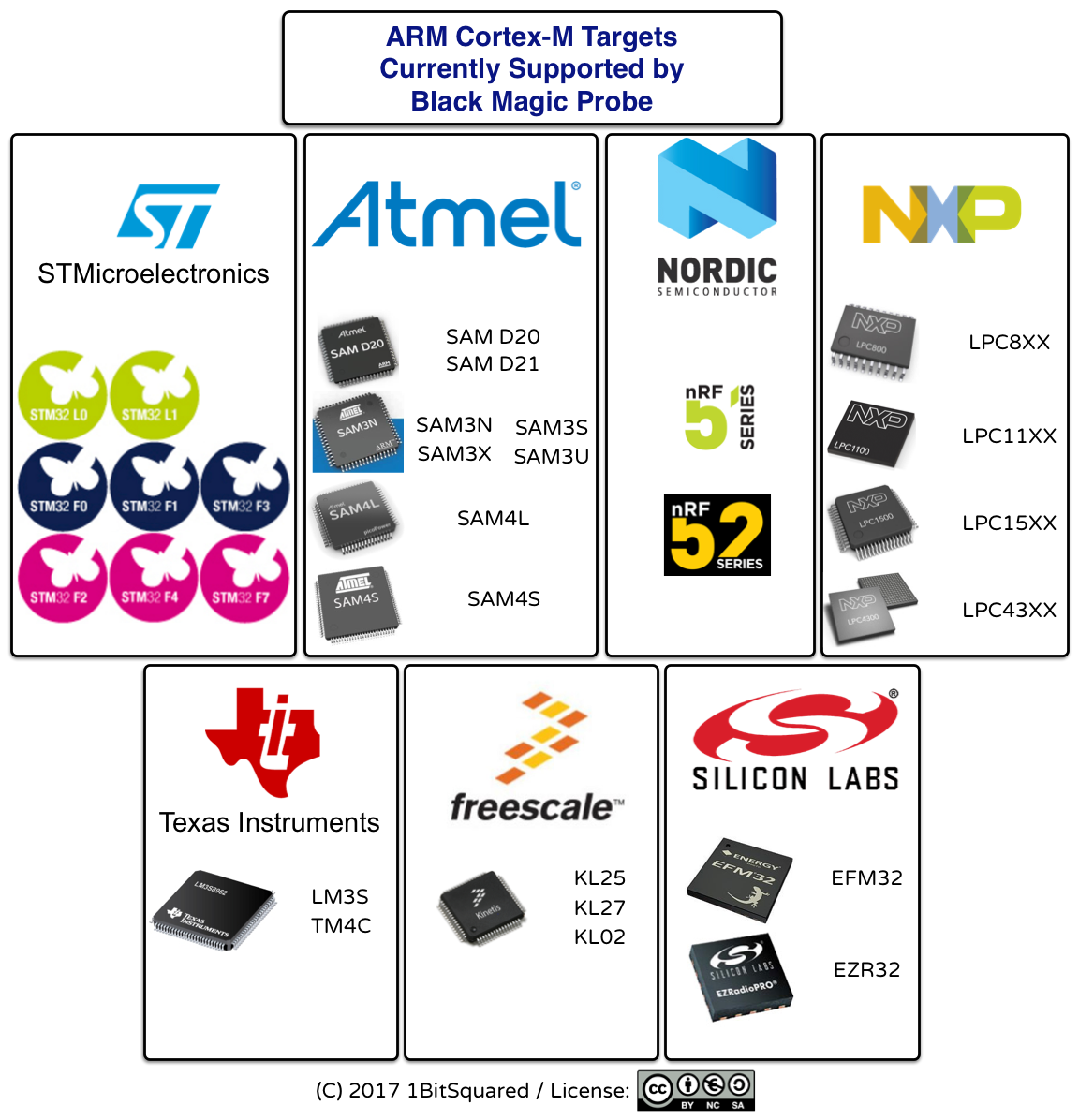
so you can flash its firmware on the blue pill to make your own. From their debugger hardware wiki page:
You can also use a generic STM32F103 board and follow these instructions.
Using the $2 (Blue Pill) STM32 board we can have a debugger that supports breakpoints. No need of OpenOCD server, as it runs a GDB server on chip directly.
An alternative SWD probe, the ST-Link v2 supports SWIM (single wire interface module) and JTAG/SWD to STM8 and STM32 microcontrollers. ST sells it for $20.83 (or a whopping $77.18 for the isolated version), but there are ST-Link v2 clones on Aliexpress for $1.81. How does the ST-Link compare to the Black Magic Probe? See the FAQ: How does the Black Magic Probe compare to the ST-Link programmer?, long story short, BMP is open source and supports more targets (not only STM32) and interfaces (not only SWD, but also JTAG). Nonetheless, that hasn’t stopped Kenjutsu: DIY ST-Link V2 programmer (SWIM & SWD.
Anyways, I followed the excellent instructions in
Converting an STM32F103 board to a Black Magic Probe. Build the Black Magic firmware for STM32F103, flash the DFU over serial, then use dfu-util to upload the firmware over USB. Reattach and system_profiler SPUSBDataType now shows the Black Magic and also two virtual serial devices appear in /dev:
$ ls /dev/cu.usbmodem*
The first is for attaching to GDB, when the blue pill is connected to a processor using SWD as follows: SWDIO=B14, SWCLK=A5. The second is a bonus free serial port, to be wired as follows: RXD=PA3, TXD=PA2. I confirmed the serial port operation by wiring it to another USB-to-serial adapter, then connecting with screen to both and typing in one, showing characters received on the other side.
Even without using SWD, having this spare USB-to-serial port converter is nice. Was looking into dedicated firmware for only performing USB-to-serial, but it isn’t necessary now that we can use the Black Magic Probe firmware and get it for free.
JTAGing an ESP32, or not
But since we do have SWD/JTAG, how about making use of it? We could debug another STM32, but the ESP32 I used in Espressif IDF IoT Development Framework on the WEMOS LOLIN32 ESP32 to drive an SSD1305 OLED display over SPI without Arduino supports JTAG. Found on the ESP32.com forums, the link to this diagram which showed GPIO14 to TMS (test mode select), GPIO12 to TDI (test data input), GPIO13 to TCK (test interface clock), GPIO15 to TDO (test data output). Check the pinout for Black Magic Probe in src/platforms/stlink/platform.h:
#define TDI_PORT	GPIOA
#define TMS_PORT	GPIOB
#define TCK_PORT	GPIOA
#define TDO_PORT	GPIOA
#define TDI_PIN		GPIO7
#define TMS_PIN		GPIO14
#define TCK_PIN		GPIO5
#define TDO_PIN		GPIO6
The “port” is the group, first letter of the pin designator (A, B, …), the pin is the number, so TMS (also used for SWDIO) is PB14, TCK (also used for SWCLK) is PA5. The silkscreen omits the “P”. All of the wiring, the STM32F103 BMP to the ESP32:
| JTAG | Blue Pill - Black Magic Probe | WEMOS LOLIN32 ESP |
|---|---|---|
| TCK | A5 | 13 |
| TDO | A6 | 15 |
| TDI | A7 | 12 |
| TMS | B14 | 14 |
Connect to the BMP using gdb from the xtensa-esp32 toolchain:
$ xtensa-esp32-elf-gdb -ex "target extended-remote /dev/cu.usbmodemE3C896E1"
(gdb) monitor
Black Magic Probe (Firmware v1.6.1-103-ga3484e3) (Hardware Version 0)
Copyright (C) 2015  Black Sphere Technologies Ltd.
License GPLv3+: GNU GPL version 3 or later <http://gnu.org/licenses/gpl.html>
Try to scan the JTAG:
(gdb) monitor jtag_scan
Target voltage: unknown
Available Targets:
No. Att Driver
No usable targets found.
Why is it not found, or a better question, is this even expected to work? Found this question in the BMP issue tracker: #278 JTAG support on ST-Link V2, answered as thus:
Neither BMP nor stock OpenOCD support ESP32. It seems, there are add-ons to openOCD to support ESP32.
The ESP-IDF Programming Guide JTAG Debugging further explains:
Espressif has ported OpenOCD to support the ESP32 processor and the multicore FreeRTOS, which will be the foundation of most ESP32 apps, and has written some tools to help with features OpenOCD does not support natively.
Building OpenOCD from Sources for MacOS explains you need to use their fork of OpenOCD in https://github.com/espressif/openocd-esp32. How does OpenOCD-ESP32 differ from the official upstream version, https://git.code.sf.net/p/openocd/code? I forked the repo and created a pull request to show the differences: 176 commits, 80 files changed, +13,468 -127. What is the common ancestor? git merge-base esp32 master pinpoints this commit from May 21, 2016. Here are all the changes Espressif added:
openocd-code $ git diff `git merge-base esp32 master`|diffstat
 .gitlab-ci.yml                                          |  199 +
 contrib/esp108-genregs.sh                               |  104
 contrib/loaders/flash/esp32/Makefile                    |  107
 contrib/loaders/flash/esp32/sdkconfig.h                 |   30
 contrib/loaders/flash/esp32/stub.ld                     |   58
 contrib/loaders/flash/esp32/stub_flasher.c              |  721 ++++
 contrib/loaders/flash/esp32/stub_flasher.h              |   37
 contrib/loaders/flash/esp32/stub_flasher_code.inc       |  618 +++
 contrib/loaders/flash/esp32/stub_flasher_data.inc       |   48
 contrib/loaders/flash/esp32/stub_flasher_image.h        |    2
 contrib/loaders/flash/esp32/stub_flasher_wrapper.inc    |    2
 contrib/loaders/flash/esp32/stub_wrapper.S              |   41
 jimtcl                                                  |    2
 src/Makefile.am                                         |    2
 src/flash/mflash.c                                      |    2
 src/flash/nand/lpc3180.c                                |   16
 src/flash/nand/mx3.c                                    |    1
 src/flash/nor/Makefile.am                               |    1
 src/flash/nor/drivers.c                                 |    2
 src/flash/nor/esp32.c                                   | 1065 ++++++
 src/flash/nor/fm3.c                                     |    4
 src/flash/nor/kinetis.c                                 |    4
 src/flash/nor/numicro.c                                 |    4
 src/flash/nor/xmc4xxx.c                                 |    4
 src/helper/command.c                                    |    1
 src/jtag/drivers/ftdi.c                                 |    4
 src/jtag/drivers/libjaylink                             |    2
 src/rtos/FreeRTOS.c                                     |  263 +
 src/rtos/Makefile.am                                    |    4
 src/rtos/ThreadX.c                                      |    6
 src/rtos/rtos.c                                         |   22
 src/rtos/rtos.h                                         |   10
 src/rtos/rtos_chibios_stackings.c                       |    6
 src/rtos/rtos_ecos_stackings.c                          |    3
 src/rtos/rtos_embkernel_stackings.c                     |    3
 src/rtos/rtos_freertos_stackings.c                      |  393 ++
 src/rtos/rtos_freertos_stackings.h                      |   35
 src/rtos/rtos_mqx_stackings.c                           |    3
 src/rtos/rtos_standard_stackings.c                      |   18
 src/rtos/rtos_standard_stackings.h                      |    2
 src/server/server.c                                     |    2
 src/svf/svf.c                                           |    2
 src/target/Makefile.am                                  |   16
 src/target/arm7_9_common.c                              |    2
 src/target/arm_adi_v5.c                                 |   10
 src/target/arm_disassembler.c                           |    1
 src/target/armv7a.c                                     |    2
 src/target/esp108.c                                     | 1497 ++++++++
 src/target/esp108.h                                     |   30
 src/target/esp108_apptrace.c                            | 2705 ++++++++++++++++
 src/target/esp108_apptrace.h                            |   48
 src/target/esp108_common.c                              |  679 ++++
 src/target/esp108_common.h                              |  290 +
 src/target/esp108_dbg_regs.h                            |  212 +
 src/target/esp108_regs.h                                |  366 ++
 src/target/esp32.c                                      | 1879 +++++++++++
 src/target/esp32.h                                      |   48
 src/target/esp32_cpu_reset_handler.S                    |   70
 src/target/image.c                                      |    3
 src/target/nds32_cmd.c                                  |    2
 src/target/target.c                                     |  311 +
 src/target/target.h                                     |   33
 src/target/target_type.h                                |   11
 tcl/board/esp-wroom-32.cfg                              |   58
 tcl/board/esp32-wrover.cfg                              |   58
 tcl/interface/ftdi/esp32_devkitj_v1.cfg                 |   13
 tcl/target/esp108.cfg                                   |  183 +
 tcl/target/esp32.cfg                                    |  160
 testing/esp/debug_backend.py                            |  275 +
 testing/esp/debug_backend_tests.py                      |  245 +
 testing/esp/run_tests.py                                |  104
 testing/esp/template_test_module.py                     |   48
 testing/esp/test_apps/gen_ut_app/Makefile               |  101
 testing/esp/test_apps/gen_ut_app/configs/default        |    1
 testing/esp/test_apps/gen_ut_app/configs/single_core    |    2
 testing/esp/test_apps/gen_ut_app/main/Kconfig.projbuild |   14
 testing/esp/test_apps/gen_ut_app/main/component.mk      |    4
 testing/esp/test_apps/gen_ut_app/main/gen_ut_app.c      |   61
 testing/esp/test_apps/gen_ut_app/sdkconfig.defaults     |    2
 testing/esp/test_bp.py                                  |   90
 testing/esp/test_exec_ctrl.py                           |   61
 testing/esp/test_step.py                                |   51
 82 files changed, 13470 insertions(+), 129 deletions(-)
but the upstream since diverged, so it doesn’t merge cleanly. There is an open issue #23 Upstream? from Nov 1st asking if there are plans to upstream. Someone would need to resolve the conflicts, across the 16 files. Many of conflicts appear to be inconsequential comments, however. Reconciling the conflicts:
Most come from this commit on ESP’s side: Fix compile errors - Implicit falls through in switch case - sprintf() buffer size. Revert it, and conflicts are down to 7 files. Besides makefiles, only three conflicting .c source files.
src/rtos/FreeRTOS.c: ESP adds FreeRTOS_post_reset_cleanup and FreeRTOS_clean, but upstream changes detect_rtos to bool. Take both changes. ESP loops over all the cores to show the current thread; upstream changes the string from “Running” to “State: Running”, take ESP’s change.
src/rtos/rtos.c: ESP introduces functions to set the current thread, upstream adds support for uc/OS-III, specifically /* threadid of 0 indicates target should choose */. Merge the two changes.
src/target/target.c: ESP adds target flasher stub, upstream adds defer-examine. Merge both but keep upstream first. alloc_working_area_try_do() also conflicts with the target flasher, changing target->working_area_phys to wa_cfg->phys and target->working_area to wa_cfg->area; take ESP’s changes.
Makefile merging is tedious. src/target/Makefile.am adds ESP108_SRC, ESP32_SRC; upstream added STM8_SRC, of course we want both. Source files now use a %D% prefix. noinst_HEADERS is now %C%_libtarget_la_SOURCES. Similar change in src/rtos/Makefile.am, add rtos_freertos_stackings.h and rtos_freertos_stackings.c to %C%_librtos_la_SOURCES. And src/flash/nor/Makefile.am. Finally, src/Makefile.am: ESP only added openocd_LDADD += -lpthread as part of SystemView support, but there are conflicts because of upstream makefile refactoring. With the new makefile system this translates to %C%_openocd_LDADD += -lpthread.
Committed the first take at this merge here. Rebuild with: ../bootstrap && ./configure && make. Oops, it failed:
openocd-code $ make
Makefile:4386: warning: overriding commands for target `check-recursive'
Makefile:3799: warning: ignoring old commands for target `check-recursive'
Makefile:4453: *** missing separator.  Stop.
mistakingly merged with a space in the makefile instead of a tab. Makefiles notoriously require tab characters. Fix it then we can start to build, but it fails:
src/rtos/rtos_ucos_iii_stackings.c:54:1: error: missing field 'custom_stack_read_fn' initializer [-Werror,-Wmissing-field-initializers]
};
This is not in a file ESP added, but it is caused by their change to add custom_stack_read_fn to the interface:
       /* Some targets have to implement their own stack read function,
        * because the stack is formatted weird or needs mangling before
        * passing it on to gdb.
        */
       int (*custom_stack_read_fn)(struct target *target, int64_t stack_ptr, const struct rtos_register_stacking *stacking, uint8_t *stack_data);
it can be null and won’t be called (null check in rtos_generic_stack_read()), so add it to all the structure initializers…actually, ucos_iii is the only one needed since ESP made the change on their end to the other stackings. Make this change, committed as part of the merge commit, and it compiles!
OK, now what? I patched OpenOCD for ESP32, but how can I add this ESP32 functionality to the Black Magic Probe firmware? CuVoodoo explains, the BMP “comes with an embedded GDB server. Thus no need to have an OpenOCD server”. 1bitsquared also says “Black Magic Probe gets rid of intermediate programs like OpenOCD or STLink server”. Unfortunately, while convenient, this limitation seems to reduce hardware support: from their FAQ:
Why is XXX not supported? In most cases because they use different specifications of JTAG debug ports. We currently only support ADIv5 devices.
ADI is the ARM Debug Interface. The ESP32 has a Tensilica Xtensa LX6 processor core, it isn’t ARM. Meh. Back to the drawing board. OpenOCD is the way to go, refer to their debug adapter hardware.
I have an ST-Link v2 clone on the way but the OpenOCD documentation notes “ST Micro has an adapter called ST-LINK. They only work with ST Micro chips, notably STM32 and STM8.”
Espressif, in ESP-IDF Programming Guide: Selecting a JTAG Adapter, of course, recommends their own development board:
The quickest and most convenient way to start with JTAG debugging is by using ESP32 WROVER KIT. Each version of this development board has JTAG interface already build in. No need for an external JTAG adapter and extra wiring / cable to connect JTAG to ESP32. WROVER KIT is using FT2232H JTAG interface operating at 20 MHz clock speed, which is difficult to achieve with an external adapter.
but they have this to say about 3rd party JTAG adapters:
If you decide to use separate JTAG adapter, look for one that is compatible with both the voltage levels on the ESP32 as well as with the OpenOCD software. The JTAG port on the ESP32 is an industry-standard JTAG port which lacks (and does not need) the TRST pin. The JTAG I/O pins all are powered from the VDD_3P3_RTC pin (which normally would be powered by a 3.3V rail) so the JTAG adapter needs to be able to work with JTAG pins in that voltage range.
On the software side, OpenOCD supports a fair amount of JTAG adapters. See http://openocd.org/doc/html/Debug-Adapter-Hardware.html for an (unfortunately slightly incomplete) list of the adapters OpenOCD works with. This page lists SWD-compatible adapters as well; take note that the ESP32 does not support SWD. JTAG adapters that are hardcoded to a specific product line, e.g. STM32 debugging adapters, will not work.
The minimal signalling to get a working JTAG connection are TDI, TDO, TCK, TMS and GND. Some JTAG debuggers also need a connection from the ESP32 power line to a line called e.g. Vtar to set the working voltage. SRST can optionally be connected to the CH_PD of the ESP32, although for now, support in OpenOCD for that line is pretty minimal.
So what hardware can do this? Seems simple enough, hardware capable of driving four signals: TDI, TDO, CK, and TMS, but surprisingly difficult, at least for me. For now, I shelved this effort, and moved on towards debugging an ARM target.
Nonetheless, the Black Magic Probe, which supports the blue pill as a host, is known to be able to debug another blue pill. I now have three blue pills, ready to try debugging a blue pill with a blue pill. Connect from the Black Magic Probe PB14 (SWDIO) to the target SWD side connector “O”, PA5 (SWCLK) to the SWD side connector “CLK”.

On your PC run gdb then scan SWD, it finds the target! Finally something that works:
(gdb) monitor swdp_scan
Target voltage: unknown
Available Targets:
No. Att Driver
 1      STM32F1 medium density
Attach using att 1, then we can disassemble and single-step instructions:
(gdb) att 1
Attaching to Remote target
warning: No executable has been specified and target does not support
determining executable automatically.  Try using the "file" command.
0x08000b56 in ?? ()
(gdb) x/10i $pc
=> 0x8000b5e:	blt.n	0x8000b54
   0x8000b60:	adds	r3, r1, #1
   0x8000b62:	uxth	r1, r3
   0x8000b64:	cmp	r1, r0
   0x8000b66:	blt.n	0x8000b50
   0x8000b68:	bx	lr
   0x8000b6a:	bl	0x8000aa8
   0x8000b6e:	b.n	0x8000bbe
   0x8000b70:	movs	r2, #1
   0x8000b72:	lsls	r1, r2, #13
(gdb) si
0x08000b54 in ?? ()
(gdb) c
Continuing.
Stepping through and setting breakpoints we can see the LED toggle. What do these instructions mean? LDR: load register on Heyrick, STR: store register. This is where the LED actually changes:
(gdb) x/10i 0x080003ea
   0x80003ea:	cbz	r2, 0x80003f0
   0x80003ec:	str	r1, [r0, #16]
   0x80003ee:	b.n	0x80003f2
=> 0x80003f0:	str	r1, [r0, #20]
   0x80003f2:	bx	lr
   0x80003f4:	str	r1, [r0, #12]
   0x80003f6:	bx	lr
   0x80003f8:	mov.w	r2, #65536	; 0x10000
   0x80003fc:	orrs	r2, r1
   0x80003fe:	str	r2, [r0, #24]
(gdb)
Cool. How about writing and debugging our own code?
Learning libopencm3
Start with the libopencm3-examples. The stm32/f1 directory has quite a few boards. Some examples will require changes for the blue pill, at least changing the LED to PC13 instead of whatever the other boards used.
Run make then I attempted to flash the ELF binary output (started with cdcacm.elf) with stm32loader, but it failed at 128 KB:
Write 256 bytes at 0x8020000
Traceback (most recent call last):
  File "stm32/stm32loader/stm32loader.py", line 453, in <module>
    cmd.writeMemory(conf['address'], data)
  File "stm32/stm32loader/stm32loader.py", line 326, in writeMemory
    self.cmdWriteMemory(addr, data[offs:offs+256])
  File "rf/stm32/stm32loader/stm32loader.py", line 202, in cmdWriteMemory
    self._wait_for_ask("0x31 programming failed")
  File "rf/stm32/stm32loader/stm32loader.py", line 88, in _wait_for_ask
    raise CmdException("NACK "+info)
__main__.CmdException: NACK 0x31 programming failed
That’s odd, how bug is this binary?
usb_cdcacm $ ls -lh cdcacm.elf
-rwxr-xr-x  1 admin  staff   252K Dec 18 21:49 cdcacm.elf
maybe I’m flashing the wrong thing. Seems dodgy. The .o file fits but barely. Surely we’re not really supposed to be flashing ELF binaries to the bootloader?
usb_cdcacm $ file *
Makefile:   ASCII text
README.md:  ASCII text
cdcacm.c:   c program text, ASCII text
cdcacm.d:   ASCII text
cdcacm.elf: ELF 32-bit LSB executable, ARM, EABI5 version 1 (SYSV), statically linked, with debug_info, not stripped
cdcacm.map: assembler source text, ASCII text
cdcacm.o:   ELF 32-bit LSB relocatable, ARM, EABI5 version 1 (SYSV), with debug_info, not stripped
for contrast, all of the blackmagic/src/*.bin files are just data. Hmm.. and miniblink compiles to 101 KB miniblink.elf, how can it be so large? Largely redundant, 29 KB gzipped. But the blue pills have only at least 64 KB flash (sometimes/often unofficially 128 KB). The complete Black Magic firmware, minus the bootloader, is 60 KB. What am I missing?
Examine the libopencm32-examples makefile:
EXAMPLE_RULES = elf

all: build

bin: EXAMPLE_RULES += bin
hex: EXAMPLE_RULES += hex
srec: EXAMPLE_RULES += srec
list: EXAMPLE_RULES += list
images: EXAMPLE_RULES += images
By default it builds ELF, but we can build binary images by typing make bin. Now that’s a lot more reasonable:
-rwxr-xr-x  1 admin  staff   680B Dec 18 23:15 miniblink.bin
-rwxr-xr-x  1 admin  staff    5824 Dec 18 23:15 cdcacm.bin
Flash with stm32loader, change BOOT0 back, then restart, unplug the serial and plug into USB in a computer. It doesn’t show up in system_profiler SPUSBDataType nor ls /dev/cu.*. Is the code even running? Time to try simpler examples.
stm32/f1/stm32-maple/miniblink is one such simple example of libopencm3. It flashes pin PA5 however, but on the blue pill it is PC13 which has the LED connected to it. Change the code to blink PC13:
--- a/examples/stm32/f1/stm32-maple/miniblink/miniblink.c
+++ b/examples/stm32/f1/stm32-maple/miniblink/miniblink.c
@@ -26,15 +26,15 @@ static void gpio_setup(void)
        /* Manually: */
        // RCC_APB2ENR |= RCC_APB2ENR_IOPCEN;
        /* Using API functions: */
-       rcc_periph_clock_enable(RCC_GPIOA);
+       rcc_periph_clock_enable(RCC_GPIOC);

        /* Set GPIO5 (in GPIO port A) to 'output push-pull'. */
        /* Manually: */
        // GPIOA_CRH = (GPIO_CNF_OUTPUT_PUSHPULL << (((5 - 8) * 4) + 2));
        // GPIOA_CRH |= (GPIO_MODE_OUTPUT_2_MHZ << ((5 - 8) * 4));
        /* Using API functions: */
-       gpio_set_mode(GPIOA, GPIO_MODE_OUTPUT_2_MHZ,
-                     GPIO_CNF_OUTPUT_PUSHPULL, GPIO5);
+       gpio_set_mode(GPIOC, GPIO_MODE_OUTPUT_2_MHZ,
+                     GPIO_CNF_OUTPUT_PUSHPULL, GPIO13);
 }

 int main(void)
@@ -62,7 +62,7 @@ int main(void)
                //      __asm__("nop");

                /* Using API function gpio_toggle(): */
-               gpio_toggle(GPIOA, GPIO5);      /* LED on/off */
+               gpio_toggle(GPIOC, GPIO13);     /* LED on/off */
                for (i = 0; i < 800000; i++)    /* Wait a bit. */
                        __asm__("nop");
        }
Build with make bin then flash miniblink.bin using stm32loader. It finishes quickly:
Bootloader version 22
Chip id: 0x410 (STM32 Medium-density)
Write 256 bytes at 0x8000000
Write 256 bytes at 0x8000100
Write 256 bytes at 0x8000200
Read 256 bytes at 0x8000000
Read 256 bytes at 0x8000100
Read 256 bytes at 0x8000200
Verification OK
Restart and boot into flash… no blinking. Fortunately we now have a JTAG/SWD probe to debug further. Attach using the Black Magic Probe:
Available Targets:
No. Att Driver
 1      STM32F1 medium density
(gdb) att 1
Attaching to Remote target
warning: No executable has been specified and target does not support
determining executable automatically.  Try using the "file" command.
0x08005216 in ?? ()
(gdb) bt
#0  0x08005216 in ?? ()
#1  <signal handler called>
#2  0x0800521c in ?? ()
#3  0xfffffffe in ?? ()
Backtrace stopped: previous frame identical to this frame (corrupt stack?)
(gdb) x/10i $pc
=> 0x8005216:			; <UNDEFINED> instruction: 0xffffffff
   0x800521a:			; <UNDEFINED> instruction: 0xffffffff
   0x800521e:			; <UNDEFINED> instruction: 0xffffffff
   0x8005222:			; <UNDEFINED> instruction: 0xffffffff
   0x8005226:			; <UNDEFINED> instruction: 0xffffffff
   0x800522a:			; <UNDEFINED> instruction: 0xffffffff
   0x800522e:			; <UNDEFINED> instruction: 0xffffffff
   0x8005232:			; <UNDEFINED> instruction: 0xffffffff
   0x8005236:			; <UNDEFINED> instruction: 0xffffffff
   0x800523a:			; <UNDEFINED> instruction: 0xffffffff
(gdb)
There isn’t any code here where the CPU is trying to execute. None at 0x08005216 either. This example is configured for the Maple Mini board, which I’m not using, rather, a generic blue pill. The stm32-maple.ld linker script starts at different offsets than the stm32-h103.ld and other boards:
/* Define memory regions. */
MEMORY
{
	rom (rx) : ORIGIN = 0x08000000, LENGTH = 128K
	ram (rwx) : ORIGIN = 0x20000000, LENGTH = 20K
}
Try the stm32/f1/stm32-h103/miniblink example instead (note that mwm opened a pull request #104 Examples for the “minimum development system” gumstick boards, what he calls gumstick boards are now commonly known as blue pill boards, way back in 2015 but some changes were requested before merging, nothingless they could serve as useful examples; until then I’ll use the stm32-h103 examples), also making the change to PC13 (from PC12, a smaller change since it is already using port C):
--- a/examples/stm32/f1/stm32-h103/miniblink/miniblink.c
+++ b/examples/stm32/f1/stm32-h103/miniblink/miniblink.c
@@ -34,7 +34,7 @@ static void gpio_setup(void)
        // GPIOC_CRH |= (GPIO_MODE_OUTPUT_2_MHZ << ((12 - 8) * 4));
        /* Using API functions: */
        gpio_set_mode(GPIOC, GPIO_MODE_OUTPUT_2_MHZ,
-                     GPIO_CNF_OUTPUT_PUSHPULL, GPIO12);
+                     GPIO_CNF_OUTPUT_PUSHPULL, GPIO13);
 }

 int main(void)
@@ -62,7 +62,7 @@ int main(void)
                //      __asm__("nop");

                /* Using API function gpio_toggle(): */
-               gpio_toggle(GPIOC, GPIO12);     /* LED on/off */
+               gpio_toggle(GPIOC, GPIO13);     /* LED on/off */
                for (i = 0; i < 800000; i++)    /* Wait a bit. */
                        __asm__("nop");
        }
Finally, it works! A successful blink:

And the binary is only 684 bytes, compared to STM32CubeMX’s 3.4 KB..not bad, I’m liking libopencm3. Lightweight.
Convenience shell scripts
To quickly and conveniently use the Black Magic Probe, I put together a couple simple shell scripts.
The first, bmp_debug.sh, runs ARM GCC with the Black Magic Probe as a remote target (note you may need to
edit the device node path for your system) and runs a JTAG and SWD scan, then drops you into gdb:
#!/bin/sh -x
arm-none-eabi-gdb -ex "target extended-remote /dev/cu.usbmodemE3C896E1" -ex "monitor jtag_scan" -ex "monitor swdp_scan"
The second, bmp_flashstm32.sh, runs stm32loader.py (edit to add the
full path on your system if necessary, also check the device node) to erase teh flash, write a .bin file,
and verify the flash; this is used for uploading new code to the target blue pill:
#!/bin/sh -x
stm32loader.py -p /dev/cu.usbmodemE3C896E3 -e -w -v $*
pill_blink
To continue on the journey to learn libopencm3 and ARM embedded programming, put together a comparison of simple LED blinking programs for CubeMX, libopencm3, libopencm3 only using register definitions, and “bare metal” (no libraries) here: https://github.com/satoshinm/pill_blink.
The CubeMX example is what I already did in STM32 Blue Pill ARM development board first look: from Arduino to bare metal programming, there is a ton of generated boilerplate code, but the salient bits calling into STM32’s hardware abstraction layer to blink the LED are:
  /* USER CODE BEGIN WHILE */
  while (1)
  {
    GPIOC->BRR |= 1<<13;
    for (int i = 0; i < 1000000; ++i) asm("nop");
    GPIOC->BSRR |= 1<<13;
    for (int i = 0; i <  500000; ++i) asm("nop");
  /* USER CODE END WHILE */
Using libopencm3 is quite simpler, since the necessary abstraction code is part of the library instead of generated in your project, here is the complete program:
#include <libopencm3/stm32/rcc.h>
#include <libopencm3/stm32/gpio.h>

int main(void) {
    rcc_periph_clock_enable(RCC_GPIOC);
    gpio_set_mode(GPIOC, GPIO_MODE_OUTPUT_2_MHZ, GPIO_CNF_OUTPUT_PUSHPULL, GPIO13);

    while(1) {
        gpio_set(GPIOC, GPIO13);
        for (int i = 0; i < 1000000; ++i) __asm__("nop");
        gpio_clear(GPIOC, GPIO13);
        for (int i = 0; i <  500000; ++i) __asm__("nop");
    }
}
This is based on a simplified stm32-h103/miniblink from the official examples. To go deeper, learning more low-level, I also replaced these function calls with direct register accesses in this example:
#include <libopencm3/stm32/rcc.h>
#include <libopencm3/stm32/gpio.h>

int main(void) {
    RCC_APB2ENR |= RCC_APB2ENR_IOPCEN;

    GPIOC_CRH = (GPIO_CNF_OUTPUT_PUSHPULL << (((13 - 8) * 4) + 2));
    GPIOC_CRH |= (GPIO_MODE_OUTPUT_2_MHZ << ((13 - 8) * 4));

    while(1) {
        GPIOC_BSRR = GPIO13;
        for (int i = 0; i < 1000000; ++i) __asm__("nop");

        GPIOC_BRR = GPIO13;
        for (int i = 0; i <  500000; ++i) __asm__("nop");
    }
}
This works identically, but produces slightly smaller code since the library functions are not needed. Can we go even lower-level? What about programming with no library at all? First step is to replace the constant definitions, this can be accomplished by running the code through the C preprocessor, arm-none-eabi-cpp pill_blink.c -DSTM32F1 -I libopencm3/include. The #includes can now be removed, however, libopencm3 provides something else crucial: the linker script.
Without the linker script, the compiler won’t know where to place any of the code and data. stm32-h103.ld in the examples defines the origin and length of the ROM and RAM, but it also includes a common libopencm3_stm32f1.ld file. This is part of libopencm3 itself, and the complete file can be found here: libopencm3/lib/stm32/f1/libopencm3_stm32f1.ld. It is reasonably complex, but a minimal linker script needs just about only this, I saved as bluepill.ld:
MEMORY
{
    rom (rx) : ORIGIN = 0x08000000, LENGTH = 128K
    ram (rwx) : ORIGIN = 0x20000000, LENGTH = 20K
}

EXTERN(vector_table);
ENTRY(reset_handler);

SECTIONS
{
    .text : {
        *(.vectors)
        *(.text*)
        . = ALIGN(4);
    } >rom
}
This defines the vector table at the beginning of the ROM, followed by the program text (code). The processor knows where to begin executing (and to handle other events) by consulting the vector table. In libopencm3, the vectors are defined in lib/cm3/vector.c, including the reset vector which copies data, performs pre-main initialization (necessary since C++ allows constructors to execute before main(), call main() itself, then execute any destructors. For a simple program much of this is unnecessary, so I just put my code into the reset vector handler. Here’s the complete bare metal C source:
void __attribute__ ((weak, naked)) reset_handler(void) {
    (*(volatile unsigned int *)(0x40021018)) |= (1 << 4);

    (*(volatile unsigned int *)(0x40011004)) |= (0x00 << (((13 - 8) * 4) + 2));
    (*(volatile unsigned int *)(0x40011004)) |= (0x02 << ((13 - 8) * 4));

    while(1) {
        (*(volatile unsigned int *)(0x40011010)) = (1 << 13);
        for (int i = 0; i < 1000000; ++i) __asm__("nop");

        (*(volatile unsigned short *)(0x40011014)) = (1 << 13);
        for (int i = 0; i < 500000; ++i) __asm__("nop");
    }
}

__attribute__ ((section(".vectors")))
struct {
    unsigned int *initial_sp_value;
    void (*reset)(void);
    void (*nmi)(void);
    void (*hard_fault)(void);
    void (*memory_manage_fault)(void);
    void (*bus_fault)(void);
    void (*usage_fault)(void);
    void (*reserved_x001c[4])(void);
    void (*sv_call)(void);
    void (*debug_monitor)(void);
    void (*reserved_x0034)(void);
    void (*pend_sv)(void);
    void (*systick)(void);
    void (*irq[68])(void);
} vector_table = {
    .reset = reset_handler,
};
This produces the smallest binary of them all, a mere 440 bytes compared to the whopping 3 KB from STM32CubeMX we started with:
| Platform | pill_blink size (bytes) |
|---|---|
| STM32CubeMX | 3496 |
| libopencm3 | 1088 |
| libopencm3 using registers | 608 |
| bare metal | 440 |
Nonetheless, some abstraction is useful, and I’m leaning most towards using the libopencm3 library as intended, since it provides a reasonable balance of abstraction vs program size.