blog
Capacitive discharge welder with 350 farad supercapacitor
by snm, January 14h, 2018
Supercapacitors can provide high current, allowing for their use in spot welding, specifically, capacitive discharge welding.
Supercap
Used this capacitor: Maxwell Technologies Inc. CAP 350F 2.7V. At an impressive 350 farads, low 2.7 volts, but a 3.2 millohm equivalent series resistance, this device can pack quite a punch. Electronics in a Nutshell ϟ posted about this same capacitor here: Charging a 350F Maxwell Ultracapacitor!.
Charge it up at 2.7 volts, when current drops off, short out the leads with a wire and watch it melt. Works in concept, now to make it generally usable.
Another cap, only 1 farad, also 2.7 volts, but with 4 Ω resistance: Nichicon CAP 1F 20% 2.7V THROUGH HOLE. Capacitance or voltage can be increased by wiring multiple of these capacitors in parallel or series, but the high equivalent series resistance is a problem for dumping high current quickly. Shorted it out, nothing interesting happens. Sticking with the 350 farads.
Buck
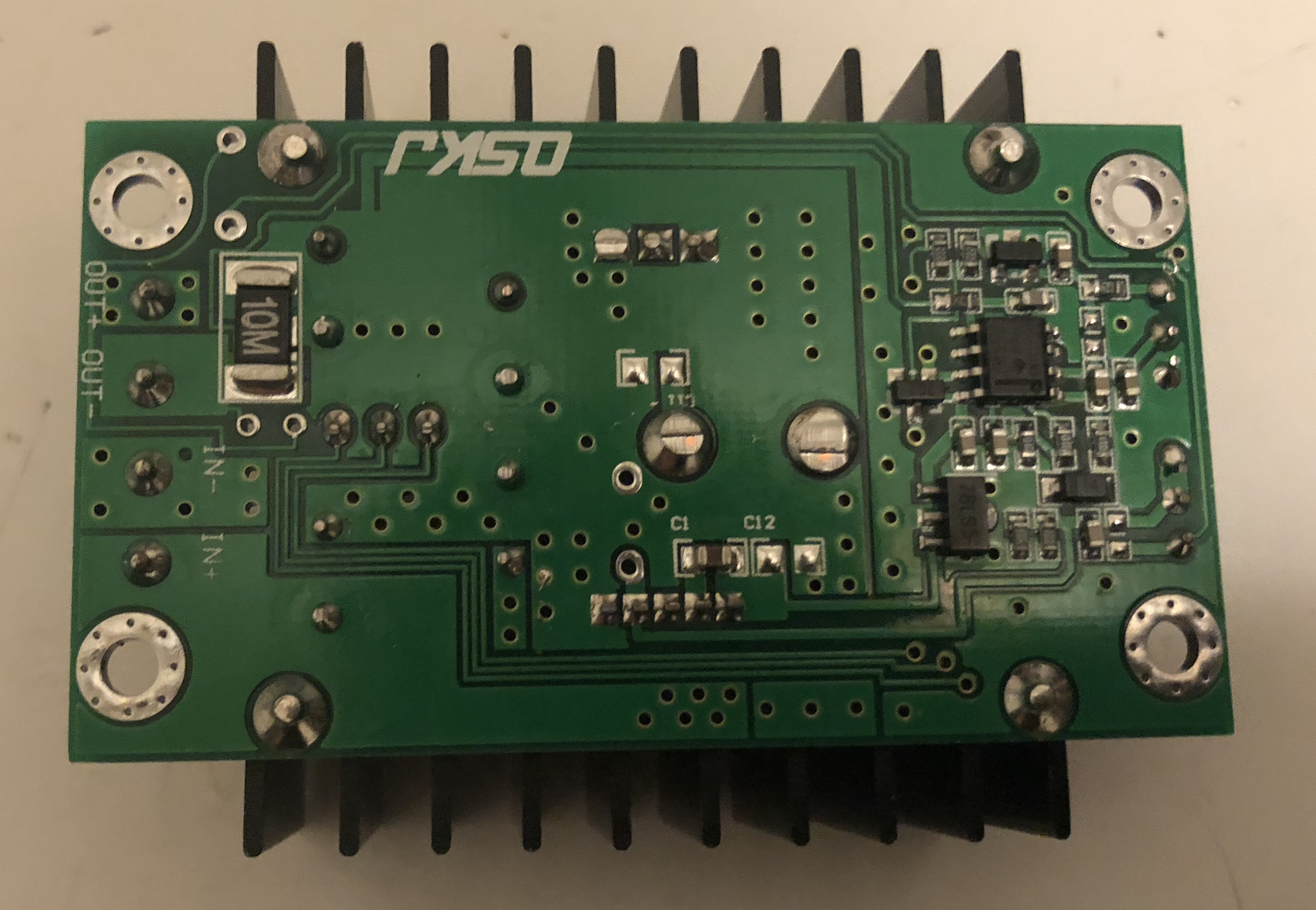
Bought an adjustable buck converter, to step down precisely to 2.7 volts, and also to limit current: DC CC Max 9A 300W Step Down Buck Converter 5-40V To 1.2-35V Power Supply Module For Arduino XL4016 LED Driver Low Output Ripple. Arrived and looks as pictured:

Screw terminals for input/output on the left, and adjustable potentiometers for voltage and current on the right. On the back, silkscreen:
Wire up the input terminals to an unregulated 12-24 V wall wart. Measure the output with a multimeter, adjust the top potentiometer until the voltage is less than 2.7 V.
To monitor capacitor voltage without breaking out the multimeter, and to display when charged: DC mini 0.36 “ Digital Red LED Display 0-100V Voltmeter 3 Wires Voltage Meter volt tester for car battery test 40% off. Since they were only 87¢ each, ordered three of these volt meters, could be useful for a lot of other projects too. Here I am connecting it to an ARM board seen in STM32 Blue Pill ARM development board first look: from Arduino to bare metal programming: black to ground, red to +5 V, yellow to +3.3 V:
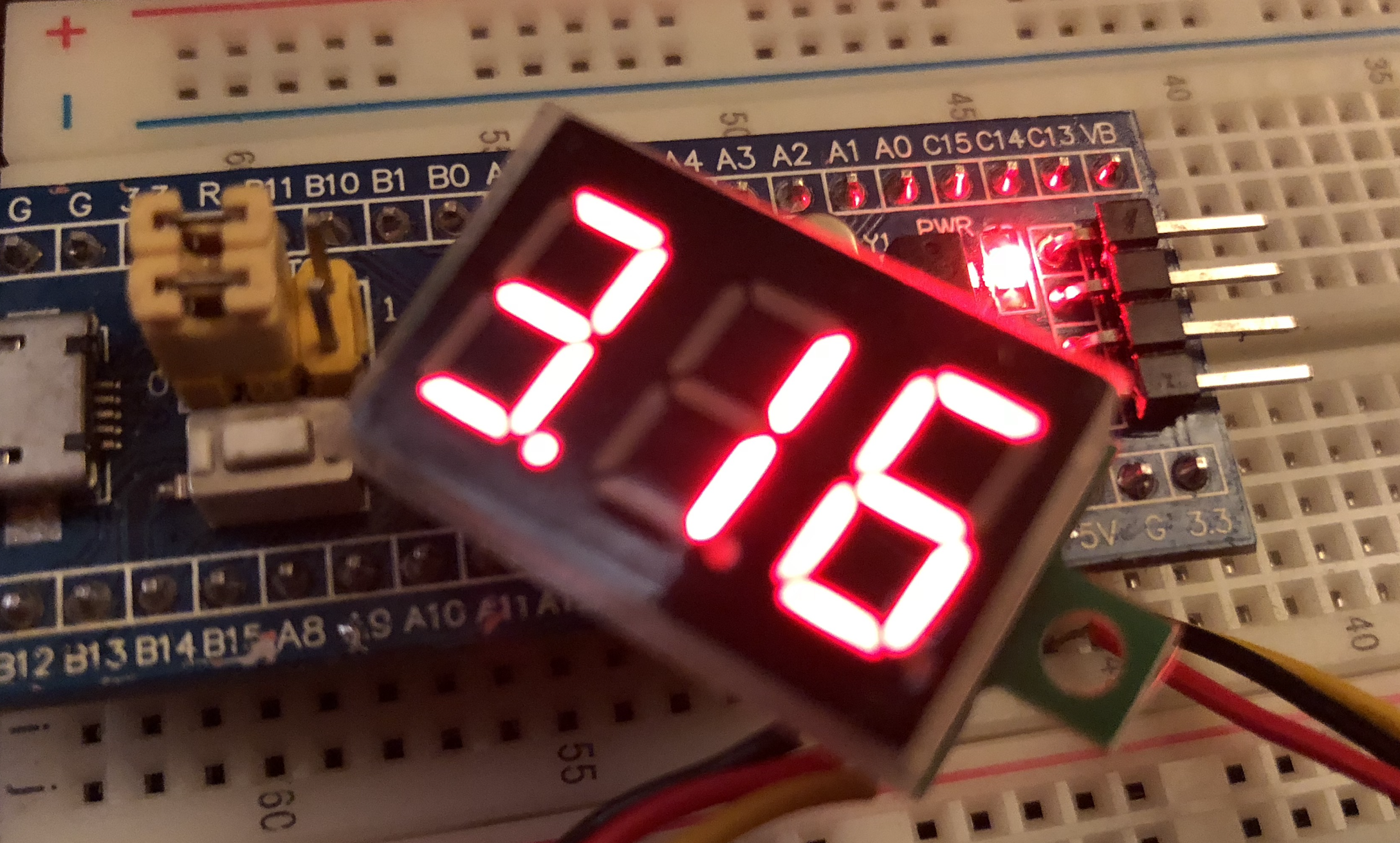
Note that these displays require 4-30 V on the red (power supply) wire, 3.3 V isn’t sufficient. Some boards like the ESP32 board in Espressif IDF IoT Development Framework on the WEMOS LOLIN32 ESP32 to drive an SSD1305 OLED display over SPI without Arduino take USB input but don’t have a +5 V pin broken out, which makes this inconvenient, since it can’t be powered with 3.3 V as it is below the 4 V minimum. But since I’m supplying the buck converter with ~16 V input, that’s enough to power both of the voltmeter displays, I connected one to each of the input and output:

Connect the output to the supercap. The voltage drops dramastically and the buck converter’s LED turns red, indicating it is limiting current (which is adjustable up to 8 amps, I have it set lower):

The output voltage increases as the capacitor charges, up to almost 2.7 V. In the later stages of charging, the current drops so the buck converter stops limiting, and the LED turns blue:

Now it is usable for welding. Disconnect the buck converter (so we don’t short it out - although it would still limit current), then run some wires from the capacitor you want to weld together. Short together and high current runs through them, heating them up until they glow red and then vaporize. If held together briefly, they heat up and join together - this is the weld.
Needs some power cables to carry this high current. The 28 AWG wires I salvaged from old CAT3 telephone cable cannot even barely handle this current. From Ohm’s law, at 2.7 volts divided by 3.2 millohms, we can expect up to 843.75 amperes!
Diode
To prevent the capacitor from charging back into the buck converter when it is off (is this necessary?), I added a diode on the buck output. Originally I wanted to use this diode:

because it looks cool, but I observed inconsistent results reading the voltage across it. Wouldn’t even register on diode mode on the multimeter. From the markings HVR-1X 3 SK 6301, look up the data sheet: HVR-1X-4 Datasheet, it is a high voltage power diode, peak reverse voltage 12000 V, max forward voltage drop: 11.0 volts, wow! Despite the kilovolt ratings, average forward current is 500 mA, max reverse current 0.3 µA. Not suitable for this low-voltage high-current application.
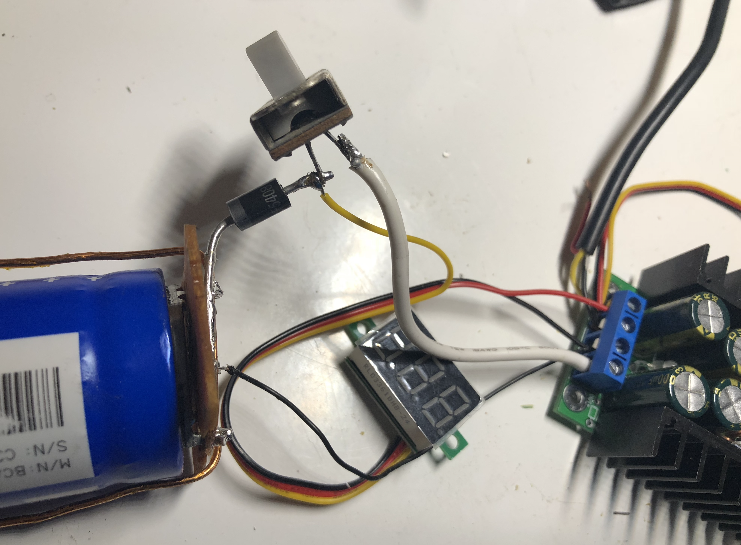
Switch to a smaller silicon diode, grabbed this one randomly labeled “F5408 G1944”, if this data sheet is to be believed: UF5408-2C3A-2CDO-27 Datasheet, then it is a 3.0 amp high-efficiency rectifier. 50 volts to 1000 volts, low forward voltage drop, high current capacity, high reliability, high surge current capability, I like the sound of that. Wire to the buck converter output, measure the output voltage:

As expected there is about a 0.7 V drop across the diode, so the buck converter has to be adjusted upwards (to output slightly less than 2.7 V, after the diode, to more completely charge the supercap).
PCB and magnet wires
To support the supercap, I wanted to mount it on a printed circuit board. Found a bit of salvaged PCB that fit, and drilled holes to make the capacitor snap in:

The middle larger terminal is negative, the three outer terminals are positives. Although it now fits, the PCB has conductive tracks on it:

These need to be removed to not short out the component. To do this, we can use a trick by inducing what Louis Rossmann calls popcorning (is your service center popcorning CPUs?), this usually occurs unintentionally when someone tries to repair a board by blowing hot air over it. The layers delaminate and bubbles occur under the traces. I happen to have a hot air gun, first unboxed in the prior blog post Youyue 858D hot air gun first look, so I used it to make popcorn, in fact, the above photo was taken after applying hot air: notice the bubbles on the right. Now they are easier to lift off and scrape off with a knife, leaving a clean blank board:

Flip the board over, push in the supercap, and solder on some thick magnet wires:

aka “enamaled wire”, this thick low-gauge wire came from a line transformer, it ought to be able to handle the current. This wire isn’t easy to work with, the enamal has to be scraped off in order to solder it, or elsewise it acts like solder mask, and it doesn’t merely burn off with heat unlike finer magnet wire. But it is workable, and I soldered two wires one, one for + (center) and another for -. Conveniently, the board has a “(+)” sign by the positive terminal (pure coincidence, I swear).
Switch
To turn or on off charging, a switch can be used. Is it needed (why not unplug the charger)? Yes, because when the charging is off, we still want to see the capacitor’s voltage on the voltmeter, and this requires power (more than the low voltage the capacitor might have). First I wired up this 120V SPST switch in series:
but there were several problems. The voltmeter sense wire was on the wrong side of the switch, so it measured the buck converter’s output voltage, when we want to measure the capacitor voltage on the other side. Fix this:

but then after some tests, the switch died. Not a straight open, but a bad connection inside the switch, it was too old anyways. Replace it with this beefier metal switch, which happens to be SPDT:

Here the switch is flipped to the right, closing the opposite terminals (center terminal is common), which is not connected, so charging is off. Flip it down and charging is enabled, as seen by the current-limiting buck converter (red LED):
The other throw of the switch will become useful for…
Bleed resistors
I connected the other side of the SPDT switch to a pushbutton and high-wattage cement resistors, across the capacitor to two 0.47 Ω (yes, milliohm) in series, borrowed from Pioneer SD-P453S Rear-Projection (RPTV) teardown: inside an 80s vintage big screen TV. Knew those resistors would come in handy. From a 31,000 volt TV set, they ought to be able to withstand power dissipation from this supercapacitor.
Since the switch’s “charging off” setting is wired to the bleed resistors, I put an additional switch in series, a pushbutton you have to press and hold to bleed off the charge. The user interface possibilities are now:
| Switch | Pushbutton | State | Description |
|---|---|---|---|
| Down | any | Charging | Power supply supplies power to the supercap, voltmeter shows charging voltage |
| Up | not pressed | Holding | No power supplied, voltmeter shows supercap charged voltage |
| Up | pressed | Discharging | Energy slowly dissipates from the supercap to the resistors |
Terminals
What could we put on the ends of the leads to make good contact? Bus bar would carry the current, but I didn’t have any, fortunately I found these heat sinks which were attached to diodes, I painstakingly desoldered them:

Heatsink desoldering takes a lot of energy, just be patient and let it warm up through the temperature-regulated soldering iron. Pumping in all that heat, the heatsinks could be removed from the diodes. The big one will make a good negative terminal. I’m not using any professional welding equipment, so the more surface area on the welding terminal leads the better, especially so they don’t burn up or oxidize and make poor contact. Are there real welding leads I could use?
Anyways for the positive lead, I used a larger yellow stranded wire, which would hopefully burn up before the longer magnet wire leads do.
Boxing it up
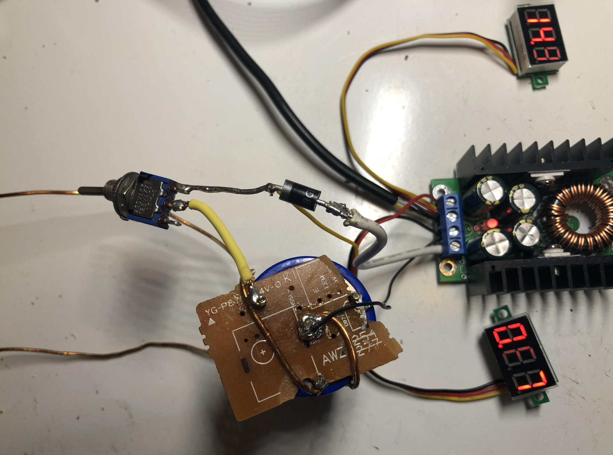
No project would be complete without a case. Here is the complete circuit out in the open:

A proper case (perhaps designed with CAD and 3d-printed?) would be ideal, but to prototype, can’t be cardboard. Reused the original box from Building a small custom Raspberry Pi Zero laptop in a cardboard box, since I replaced it in Custom laptop upgrades: internal breadboard, power indicator, and larger case and had the small box leftover. The components fit in perfectly:
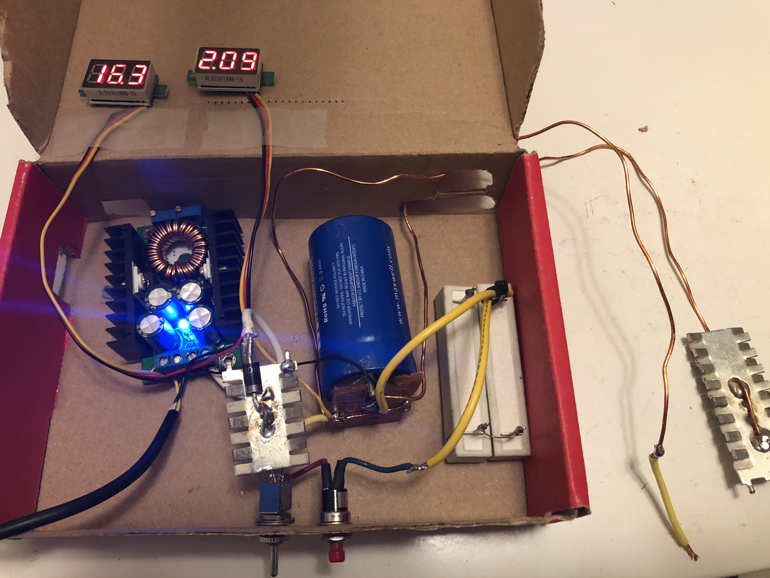
Taped on the top are the voltmeters for the power supply and capacitor, respectively, the inside the box is the buck converter (power coming from a wall power adapter, wires run outside the box), the diode with heatsink, the supercapacitor itself, bleed resistors. On the front panel, both of the switches I used conveniently have washers and nuts, so I fastened them through the cardboard panel: left switch is charging on/off, right is the discharge pushbutton. Outside of the back come the leads for the welder.
Close the box and it packs away neatly:

Can it weld?
All this work, can this welder actually weld? A reasonable question.
So I attempted to make some welds, but realized I don’t actually have anything I need to weld. Soldering does the job most of the time. Experimented a bit, and some sticking action could be felt, but I’m not really well versed on the technique. The welder can, at least, melt wires and printed circuit board traces.
This is just a random experient in high current. Another project, by tatus1969 on eevblog forums, may be more practical and complete: kWeld - “Next level” DIY battery spot welder. Nonetheless, if I ever need a low-voltage high-current source I now have one.